Table of Contents
Advertisement
Available languages
Available languages
Advertisement
Chapters
Table of Contents

Related Manuals for DAB AQUATWIN TOP 132


Summary of Contents for DAB AQUATWIN TOP 132
- Page 1 ISTRUZIONI PER L'INSTALLAZIONE E LA MANUTENZIONE INSTRUCTIONS POUR L'INSTALLATION ET LA MAINTENANCE INSTRUCTIONS FOR INSTALLATION AND MAINTENANCE INSTALLATIONSANWEISUNG UND WARTUNG INSTRUCTIES VOOR INGEBRUIKNAME EN ONDERHOUD AQUATWIN TOP 132 AQUATWIN TOP 40/50 AQUATWIN TOP 40/80...
- Page 2 pag. ITALIANO page FRANÇAIS page ENGLISH Seite DEUTSCH NEDERLANDS bladz...
-
Page 3: Table Of Contents
ITALIANO INDICE Legenda ..............................2 Generalità ..............................2 Sicurezza ............................2 Responsabilità ........................... 2 Avvertenze Particolari ........................3 OGGETTO DELLA FORNITURA ......................3 DESCRIZIONE GENERALE DEL SISTEMA .................... 4 ... -
Page 4: Legenda
ITALIANO 1. LEGENDA Nel presente documento si utilizzeranno i seguenti simboli per evidenziare situazioni di pericolo: Situazione di pericolo generico. Il mancato rispetto delle prescrizioni che lo seguono può provocare danni alle persone e alle cose. Situazione di pericolo shock elettrico. Il mancato rispetto delle prescrizioni che lo seguono può... -
Page 5: Avvertenze Particolari
ITALIANO Avvertenze Particolari Prima di intervenire sulla parte elettrica o meccanica dell’impianto togliere sempre la tensione di rete. Attendere lo spegnimento delle spie luminose sul pannello di controllo prima di aprire l’apparecchio stesso. Il condensatore del circuito intermedio in continua resta carico con tensione pericolosamente alta anche dopo la disinserzione della tensione di rete. -
Page 6: Descrizione Generale Del Sistema
ITALIANO 4. DESCRIZIONE GENERALE DEL SISTEMA L’unità AQUATWIN TOP serve per la gestione e distribuzione dell’acqua piovana. L’unità rileva gli eventuali guasti nel sistema di raccolta sia dell’acqua piovana che della rete, e apporta le correzioni per garantire il corretto funzionamneto dell’impianto (ovvero non fa mancare mai l’acqua alle utenze identificate). Avvisa in caso anomalia e indica il tipo di problema rilevato. -
Page 7: Dati Tecnici
ITALIANO 5. DATI TECNICI AQUATWIN AQUATWIN AQUATWIN TOP 132 TOP 40/50 TOP 40/80 Portata (lt/min) max 80+80 80+80 120+120 Prevalenza Hm max 57,7 Temperatura del liquido Da +5°C a +35°C Da +5°C a +35°C Da +5°C a +35°C pompato Pressione massima del sistema 10 bar 10 bar 10 bar... - Page 8 ITALIANO Collegamento in aspirazione: Il sitema AQUATWIN TOP da la possibilità di gestire una o due serbatoi separati di raccolta acqua piovana. Per il collegamento di un unico serbatoio di raccolta procedere con il collegamento delle due aspirazioni separate che dovranno essere riportate singolarmente alla cisterna. Installazione: Posizionare l’AQUATWIN TOP in un luogo ben areato, protetto dalle intemperie e con una temperatura ambiente non superiore a 40°C, su un piano regolare, in caso non fosse possibile, utilizzare i piedini...
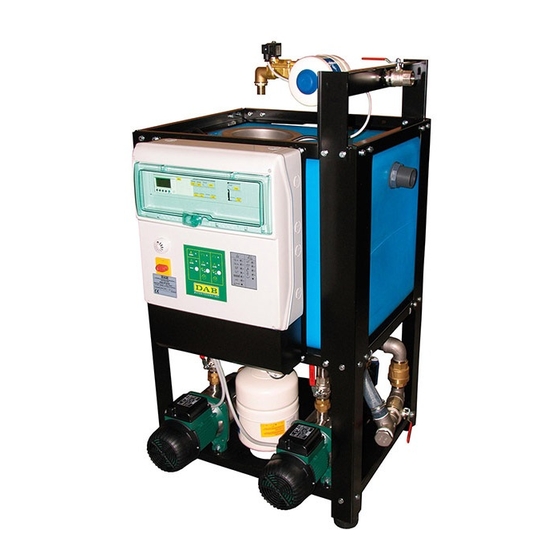
- Page 9 ITALIANO Rif. 1 Alimentazione dalla rete civile Rif. 2 Collegamento troppo pieno Rif. 3 Collegamento utenze (collegabile a dx Rif. 4 Collegamento aspirazione cisterne raccolta acqua o sx) piovana...
-
Page 10: Collegamenti Elettrici
ITALIANO 7. COLLEGAMENTI ELETTRICI Assicurarsi che l’interrutore generale del quadro di distribuzione di energia sia in posizione OFF (0) e che nessuno possa ripristinare accidentalmente il funzionamento, prima di procedere al collegamento dei cavi di alimentazione ai morsetti: L – N all’interruttore sezionatore QS1. SI RACCOMANDA UN CORRETTO E SICURO COLLEGAMENTO A TERRA DELL’IMPIANTO COME RICHIESTO DALLE NORMATIVE VIGENTI IN MATERIA. - Page 11 ITALIANO Morsetti di collegamento segnalazione stato elettrovalvola tre vie (EV1) 12 – 13 – Caratteristiche elettriche:24V AC 10mA, impedenza max. 55kOhm Morsetti di collegamento per alimentazione valvola a tre vie (EV2) 15 – 16 – Caratteristiche elettriche:230V AC 1A uscita protetta da fusibili Morsetti di collegamento segnalazione stato elettrovalvola tre vie (EV2) 18 –...
-
Page 12: Collegamento Elettrico E Settagio Per Una Vasca
ITALIANO 9. COLLEGAMENTO ELETTRICO E SETTAGIO PER UNA VASCA Per il funzionamento dell’AQUATWIN TOP in configurazione con un’unica cisterna di raccolta dell’acqua piovana procedere nel seguente modo: Collegare il galleggiante (- G1) presente nella cisterna della raccolta acqua piovana ai morsetti ( 1- 2 ) e settare la centralina (MC1) in modalità... - Page 13 ITALIANO Settaggi e funzionalità centralina gestione FUNZIONE Descrizione della funzione Tasti di selezzione funzioni Utilizzando il tasto( ) si selezziona la funzione una o due TANK/TANKS, premendo ripetutamente questo tasto viene visualizzato nello schermo la funzionalità desiderata. In funzione “1TANK” il sistema viene gestito da un singolo galleggiante posto nella cisterna, le EV1 e EV2 gestiscono l’aspirazione contemporanemente, gestendo l’acqua piovana o di rete.
-
Page 14: Pannello Frontale Di Controllo Pompe
ITALIANO PANNELLO FRONTALE DI CONTROLLO POMPE Rif. Funzione Indicazione luminosa bianca che segnala il corretto funzionamento dei circuiti ausiliari. Indicazione luminosa rossa che segnala allarme generico. Pulsante RESET allarmi. Elettropompa P1 Indicazione luminosa verde: luce accesa fissa che segnala pompa in moto. Indicazione luminosa verde: luce accesa lampeggiante che segnala pompa non disponibile. -
Page 15: Regolazione Quadro Controllo Pompe
ITALIANO REGOLAZIONE QUADRO CONTROLLO POMPE Prima di procedere con la regolazione, togliere la tensione di rete agendo sul sezionatore QS1. Per accedere al pannello interno svitare le viti, capovolgere il coperchio del quadro elettrico verso il basso e agire sui comandi. Rif. -
Page 16: Protezioni Ed Allarmi Quadro
ITALIANO PROTEZIONI ED ALLARMI QUADRO Le protezioni e gli allarmi vengono segnalati a bordo quadro tramite l’accensione dei relativi led luminosi e a distanza tramite i relè Q1, Q2, Q3. Tabella generale allarmi: segnalazioni e contatti Segnalazione led Proprietà dell’allarme Segnalazione remota pannello frontale Nome allarme/anomalia... - Page 17 ITALIANO Allarme Acqua = rappresenta un allarme legato alla marcia a secco (troppo pieno, sovra-pressione impianto ecc.). Allarme Pompa = rappresenta un allarme legato alla salvaguardia della pompa (protezione termica pompa, sovracorrente ecc.). Allarme Autoripristinabile = il centralino riattiva la pompa se viene rimossa la causa che ha generato l’allarme,oppure nei casi in cui questo non è...
- Page 18 FRANÇAIS INDEX LÉGENDE ..............................17 GÉNÉRALITÉS ............................17 Sécurité ............................17 Responsabilités ..........................17 Recommandations particulières....................18 OBJET DE LA FOURNITURE ......................... 18 Description générale du système ......................19 ...
- Page 19 FRANÇAIS 1. LÉGENDE Dans le présent document nous utiliserons les symboles suivants pour indiquer les situations de danger : Situation de danger générique. Le non-respect des prescriptions qui accompagnent ce symbole peut provoquer des dommages aux personnes et aux biens. Situation de danger de décharge électrique.
- Page 20 FRANÇAIS fait fonctionner au-delà des valeurs de fonctionnement conseillées ou en contraste avec d’autres dispositions contenues dans ce manuel. Recommandations particulières Avant d’intervenir sur la partie électrique ou mécanique de l’installation couper toujours la tension de secteur. Attendre l’extinction des voyants sur le panneau de commande avant d’ouvrir l’appareil.
- Page 21 FRANÇAIS 4. DESCRIPTION GENERALE DU SYSTEME L’unité AQUATWIN TOP sert à la gestion et à la distribution de l’eau de pluie. L’unité détecte les éventuelles pannes dans le système collecteur, tant de l’eau de pluie que de l’eau de ville, et apporte les corrections nécessaires pour garantir le fonctionnement correct de l’installation (afin d’assurer en permanence la distribution d’eau aux utilisations identifiées).
- Page 22 FRANÇAIS 5. DONNÉES TECHNIQUES AQUATWIN AQUATWIN AQUATWIN TOP 132 TOP 40/50 TOP 40/80 Débit (l/min) max. 80+80 80+80 120+120 Hauteur d’élévation Hm max. 57,7 Température du liquide pompé De +5 °C à +35 °C De +5 °C à +35 °C De +5 °C à...
- Page 23 FRANÇAIS Raccord en aspiration Le système AQUATWIN TOP permet de gérer un ou deux réservoirs séparés de collecte d’eau de pluie. En présence d’un unique réservoir collecteur, les deux aspirations séparées devront être raccordées à la citerne de manière distincte. Installation Positionner l’AQUATWIN TOP dans un endroit bien aéré, à...
- Page 24 FRANÇAIS Réf. 1 Alimentation réseau eau de ville Réf. 2 Raccord trop-plein Réf. 3 Raccord utilisations (possible à droite ou à Réf. 4 Raccord aspiration citernes collecte eau de gauche) pluie...
- Page 25 FRANÇAIS 7. BRANCHEMENTS ÉLECTRIQUES S’assurer que l'interrupteur général du tableau de distribution de l’énergie est sur OFF (0), et que personne ne peut rétablir accidentellement le fonctionnement, avant de procéder à la connexion des câbles d’alimentation aux bornes : L – N à...
- Page 26 FRANÇAIS Bornes de connexion signalisation état électrovanne à trois voies (EV1) 12 – 13 – Caractéristiques électriques : 24 Vca 10 mA, impédance max. 55 kOhm Bornes de connexion pour alimentation vanne à trois voies (EV2) 15 – 16 – Caractéristiques électriques : 230 Vca 1 A, sortie protégée par fusibles Bornes de connexion signalisation état électrovanne à...
- Page 27 FRANÇAIS 9. BRANCHEMENT ÉLECTRIQUE ET RÉGLAGE POUR UN RÉSERVOIR Pour le fonctionnement de l’AQUATWIN TOP dans la configuration avec une seule citerne de collecte de l’eau de pluie, procéder de la façon suivante : Connecter le flotteur (-G1) présent dans la citerne de collecte d’eau de pluie aux bornes (1-2) et régler le coffret (MC1) dans la modalité...
- Page 28 FRANÇAIS Réglages et fonctionnement coffret de gestion FONCTION Description de la fonction Touches de sélection fonctions En utilisant la touche ( ) on sélectionne la fonction un ou deux TANK(S), en appuyant plusieurs fois sur cette touche, l’écran affiche la fonction désirée. Avec la fonction «...
- Page 29 FRANÇAIS PANNEAU FRONTAL DE CONTRÔLE POMPE Réf. Fonction Voyant blanc qui signale le fonctionnement correct des circuits auxiliaires. Voyant rouge qui signale une alarme générique. Touche RÉINITIALISATION alarmes. Électropompe P1 Voyant vert : la lumière fixe signale que la pompe est en marche. Voyant vert : la lumière clignotante signale que la pompe n’est pas disponible.
- Page 30 FRANÇAIS RÉGLAGE TABLEAU CONTRÔLE POMPES Avant de procéder au réglage, couper la tension de secteur en agissant sur le sectionneur QS1. Pour accéder au panneau interne, dévisser les vis, rabattre le couvercle du coffret électrique vers le bas et agir sur les commandes. Réf.
- Page 31 FRANÇAIS PROTECTIONS ET ALARMES COFFRET Le protections et les alarmes sont signalées sur le coffret par l’allumage des leds correspondantes et à distance, par l’intermédiaire des relais Q1, Q2, Q3. Tableau général des alarmes : signalisations et contacts Signalisation led Propriété...
- Page 32 FRANÇAIS Alarme eau = représente une alarme liée à la marche à sec (trop-plein, surpression installation etc.). Alarme pompe = représente une alarme liée à la sauvegarde de la pompe (protection thermique pompe, surintensité etc.). Alarme Auto-réarmable = le coffret réactive la pompe si la cause qui a provoqué l’alarme est éliminée ou bien, quand ce n’est pas possible, il effectue des tentatives à...
- Page 33 ENGLISH INDEX KEY ................................32 General ..............................32 Safety ..............................32 Responsibility ..........................32 Particular warnings ......................... 33 OBJECT OF THE SUPPLY ........................33 GENERAL DESCRIPTION OF THE SYSTEM ..................34 ...
- Page 34 ENGLISH 1. KEY In this document the following symbols will be used to avoid situations of ranger: Situation of general danger. Failure to respect the instructions that follow may cause harm to persons and property. Situation of electric shock hazard. Failure to respect the instructions that follow may cause a situation of grave risk for personal safety.
- Page 35 ENGLISH Particular warnings Always switch off the mains power supply before working on the electrical or mechanical part of the system. Wait for the warning lights on the control panel to go out before opening the appliance. The capacitor of the direct current intermediate circuit remains charged with dangerously high voltage even after the mains power has been turned off.
- Page 36 ENGLISH 4. GENERAL DESCRIPTION OF THE SYSTEM The AQUATWIN TOP unit is used for the management and distribution of rain water. The unit detects the lack of water in both rain water and mains collection system and corrects it to guarantee that the system operates correctly (or rather, it never lets the identified users run out of water).
- Page 37 ENGLISH 5. TECHNICAL DATA AQUATWIN AQUATWIN AQUATWIN TOP 132 TOP 40/50 TOP 40/80 Max flow rate (lt/min) 80+80 80+80 120+120 Head Hm max 57,7 Pumped liquid temperature Da +5°C a +35°C Da +5°C a +35°C Da +5°C a +35°C Maximum system pressure 10 bar 10 bar 10 bar...
- Page 38 ENGLISH Connection on intake: The AQUATWIN TOP system offers the possibility of managing one or two separate rain water collection tanks. For the connection of a single collection tank, make the connection of the two separate intakes which must be taken individually to the tank. Installation: Place the AQUATWIN TOP in a well ventilated place, protected from unfavourable weather conditions, and with an environment temperature not higher than 40°C, on an even surface;...
- Page 39 ENGLISH Ref. 1 Supply from the mains Ref. 2 Overflow connection Ref. 3 Utilities connection (fitted on right or left) Ref. 4 Suction connection of rain water collection tank...
- Page 40 ENGLISH 7. ELECTRICAL CONNECTIONS Ensure that the main switch on the power distribution panel is in OFF position (0) and that no one can switch on the power accidentally before connecting the power cables to the terminals: L – N to the isolating switch QS1. THE SYSTEM MUST BE CORRECTLY AND SAFELY EARTHED AS REQUIRED BY THE REGULATIONS IN FORCE.
- Page 41 ENGLISH Connecting terminals for supplying the three-way valve (EV2) 15 – 16 – Electrical characteristics: 230V AC 1A outlet protected by fuses Connecting terminals for indicating status of three-way solenoid valve (EV2) 18 – 19 – Electrical characteristics: 24V AC 10mA, max. impedance 55kOhm Connecting terminals for overflow control float in drinking water storage tank 21 –...
- Page 42 ENGLISH 9. ELECTRICAL CONNECTION AND SETTING FOR ONE TANK For operation of the AQUATWIN TOP in configuration with a single rain water collection tank, proceed as follows: Connect the float (- G1) in the rain water collection tank to the terminals ( 1- 2 ) and set the control unit (MC1) in 1 TANK mode with the button ( N.B.
- Page 43 ENGLISH Settings and functions of the management control unit FUNCTION Function description Function selection buttons Using the ( ) button, select the one or two TANK/TANKS function, pressing this button repeatedly will display the desired function on the screen. In “1TANK” function the system is managed by a single float placed in the tank, EV1 and EV2 manage suction at the same time, managing rain water or mains water.
- Page 44 ENGLISH PUMP FRONT CONTROL PANEL Ref. Function White warning light indicating correct operation of the auxiliary circuits. Red warning light indicating a general alarm. Alarm RESET button. Electropump P1 Green warning light: fixed light indicating pump running. Green warning light: blinking light indicating pump not available. Yellow warning light indicating pump P1 malfunction alarm Button for manual control or deactivation of pump P1: - if held down for more than 3 seconds, allows the pump to be switched on manually,...
- Page 45 ENGLISH ADJUSTING THE PUMP CONTROL PANEL Before starting regulation, switch off the mains power by means of the insulating switch QS1. To access the internal panel, slacken the screws, turn the cover of the electric panel downwards and operate the commands. Ref.
- Page 46 ENGLISH PROTECTIONS AND PANEL ALARMS The protections and the alarms are indicated on the panel by the lighting of the respective leds and at a distance by the relays Q1, Q2, Q3. General alarms table: signals and contacts Led signal Alarm properties Remote signal on front board...
- Page 47 ENGLISH Water alarm = represents an alarm linked with dry running (overflow, system excess pressure, etc.). Pump alarm = represents an alarm linked with pump protection (pump thermal protection, current overload, etc.). Self-resettable alarm = the control unit reactivates the pump if the cause that generated the alarm is removed, or in cases where this is not possible it makes attempts at intervals.
- Page 48 DEUTSCH INHALTSVERZEICHNIS LegendE ..............................47 Allgemeines ............................47 Sicherheit ............................47 Haftung ............................. 48 Sonderhinweise ..........................48 GEGENSTAND DER LIEFERUNG ......................48 Allgemeine Beschreibung des Systems ....................49 ...
-
Page 49: Legende
DEUTSCH 1. LEGENDE Das vorliegende Dokument weist mit den folgenden Symbolen auf bestimmte Gefahrensituationen hin: Allgemeine Gefahrensituation. Die Nichteinhaltung der neben dem Symbol stehenden Vorschriften kann Personen- und Sachschäden verursachen. Stromschlaggefahr. Die Nichteinhaltung der neben dem Symbol stehenden Anweisungen kann schwerwiegende Risiken für die Unversehrtheit von Personen verursachen. 2. -
Page 50: Haftung
DEUTSCH Haftung Der Hersteller haftet nicht für die mangelhafte Funktion der Maschine oder etwaige von ihr verursachte Schäden, wenn diese manipuliert, verändert oder über die Daten des Geräteschilds hinaus betrieben wurde, oder andere in diesem Handbuch enthaltenen Anweisungen nicht befolgt wurden. Sonderhinweise Bevor auf die Elektrik oder Mechanik zugegriffen wird, muss immer die Spannungsversorgung unterbrochen werden. -
Page 51: Allgemeine Beschreibung Des Systems
DEUTSCH 4. ALLGEMEINE BESCHREIBUNG DES SYSTEMS Die Einheit AQUATWIN TOP dient zur Verwaltung und Verteilung von Regenwasser. Die Einheit nimmt eventuelle Defekte im Sammelsystem sowohl von Regenwasser als auch des Wassernetzes wahr und führt die Berichtigungen aus, um den korrekten Betrieb der Anlage zu gewährleisten (bzw. -
Page 52: Technische Daten
DEUTSCH 5. TECHNISCHE DATEN AQUATWIN AQUATWIN AQUATWIN TOP 132 TOP 40/50 TOP 40/80 Max. Fassungsvermögen 80+80 80+80 120+120 (l/min) Förderhöhe Hm max. 57,7 Temperatur der Von +5°C bis +35°C Von +5°C bis +35°C Von +5°C bis +35°C gepumpten Flüssigkeit Höchstdruck der Anlage 10 bar 10 bar 10 bar... - Page 53 DEUTSCH Sauganschluss: Das System AQUATWIN TOP ermöglicht das Management von einem oder zwei getrennten Regenwassertanks. Für den Anschluss von nur einem Tank werden di beiden separaten Saugleitungen einzeln mit der Zisterne verbunden. Installation: AQUATWIN TOP wird an einem gut belüfteten, wettergeschützten Raum mit einer Umgebungstemperatur unter 40°C auf einer ebenen Fläche aufgestellt;...
- Page 54 DEUTSCH Bez. 1 Versorgung vom Netz Bez. 2 Überlaufanschluss Bez. 3 Verbraucheranschluss (rechts oder Bez. 4 Anschluss für Ansaugen aus den links) Regenwasserzisternen...
-
Page 55: Elektroanschlüsse
DEUTSCH 7. ELEKTROANSCHLÜSSE Sicherstellen, dass sich der Hauptschalter der Verteilertafel auf der Position OFF (0) befindet und niemand die Funktion unerwartet wiederherstellen kann, bevor die Versorgungsdrähte an die folgenden Klemmen angeschlossen werden: L – N zum Trennschalter QS1. DIE VORSCHRIFTSMÄSSIGE UND SICHERE ERDUNG SICHERSTELLEN. SICHERSTELLEN, DASS DER FEHLERSTROMSCHUTZSCHALTER DER ANLAGE KORREKT BEMESSEN IST. - Page 56 DEUTSCH Elektrische Charakteristiken: 24V AC 10 mA, max. Impedanz 55 kOhm – 14 Anschlussklemmen für Speisung des 3-Wege-Ventils (EV2) 15 – 16 Elektrische Charakteristiken: 230V AC 1A Ausgang mit Sicherungen – 17 Anschlussklemmen Statusanzeige 3-Wege-Ventil (EV2) 18 – 19 Elektrische Charakteristiken: 24V AC 10 mA, max. Impedanz 55 kOhm –...
-
Page 57: Elektroanschluss Und Einstellung Für Ein Becken
DEUTSCH 9. ELEKTROANSCHLUSS UND EINSTELLUNG FÜR EIN BECKEN Für die Funktion von AQUATWIN TOP in der Konfiguration mit nur einer Regenwasserzisterne, wie folgt vorgehen: Den Schwimmer (- G1) der Regenwasserzisterne an die Klemmen ( 1- 2 ) anschließen und das Steuergerät (MC1) mit der Taste ( ) auf die Modalität 1 TANK einstellen. - Page 58 DEUTSCH Einstellung und Funktion des Steuergeräts FUNKTION Funktionsbeschreibung Tasten zur Selektion der Funktionen Mit der Taste ( ) wird die Funktion 1 oder 2 TANK/TANKS selektiert; bei wiederholtem Drücken der Taste wird auf dem Bildschirm die gewünschte Funktionsweise angezeigt. Mit der Funktion „1TANK” wird das System von einem einzelnen Schwimmer in der Zisterne gesteuert, die Ventile EV1 und EV2 verwalten das gleichzeitige Ansaugen von Regenwasser oder Leitungswasser.
-
Page 59: Frontales Steuerpaneel Der Pumpen
DEUTSCH FRONTALES STEUERPANEEL DER PUMPEN Bez. Funktion Weiße Leuchtanzeige für korrekte Funktion der Hilfskreise. Rote Leuchtanzeige für allgemeinen Alarm. RESET-Taste der Alarme. Elektropumpe P1 Grüne Kontrolllampe: bleibend eingeschaltetes Licht für laufende Pumpe. Grüne Kontrolllampe:b linkendes Licht für nicht verfügbare Pumpe. Gelbe Leuchtanzeige für Alarm wegen Funktionsstörung der Pumpe P1. -
Page 60: Einstellung Des Steuerpaneels Der Pumpen
DEUTSCH EINSTELLUNG DES STEUERPANEELS DER PUMPEN Vor dem Einstellen mit dem Trennschalter QS1 die Netzspannung abschalten. Für den Zugriff auf das innere Paneel die Schrauben aufschrauben, den Deckel der Schalttafel nach unten klappen und auf die Steuerteile einwirken. Bez. Funktion Kontrolllampen für Aktivierung der Digitaleingänge (N-A-B-C-R) Trimmer für die Regulierung der Anlage (Imax –... -
Page 61: Schutzvorrichtungen Und Alarme Der Schalttafel
DEUTSCH SCHUTZVORRICHTUNGEN UND ALARME DER SCHALTTAFEL Die Schutzvorrichtungen und die Alarme werden an der Schalttafel mittels Einschalten der entsprechenden LEDs, und entfernt mittels der Relais Q1, Q2, Q3 signalisiert. Haupttabelle der Alarme: Signale und Kontakte LED-Anzeige Eigenschaft des Alarms Fernanzeige Frontpaneel Name Alarm/Anomalie Alarm... - Page 62 DEUTSCH Wasseralarm = steht für einen Alarm wegen Trockenlauf (Überlauf, Überdruck Anlage, usw.). Pumpenalarm = steht für einen Alarm zum Schutz der Pumpe (Wärmeschutz der Pumpe, Überstromschutz, usw.). Rücksetzbarer Alarm = das Steuergerät aktiviert die Pumpe erneut, sobald die den Alarm auslösende Ursache beseitigt ist, oder führt, falls dies nicht möglich ist, Versuche nach bestimmten Intervallen durch.
- Page 63 NEDERLANDS INHOUD Legenda ..............................62 Algemene informatie ..........................62 Veiligheid ............................62 Verantwoordelijkheid ........................63 Bijzondere aanwijzingen ........................ 63 ONDERWERP VAN DE LEVERING ......................63 Algemene beschrijving van het systeem ..................... 64 ...
-
Page 64: Legenda
NEDERLANDS 1. LEGENDA In dit document worden de volgende symbolen gebruikt om gevaarlijke situaties aan te duiden: Situatie met algemeen gevaar. Veronachtzaming van de voorschriften die na dit symbool volgen kan persoonlijk letsel of materiële schade tot gevolg hebben. Situatie met gevaar voor elektrische schok. Veronachtzaming van de voorschriften die na dit symbool volgen kan een situatie met ernstig risico voor de gezondheid van personen tot gevolg hebben. -
Page 65: Verantwoordelijkheid
NEDERLANDS Verantwoordelijkheid De fabrikant is niet aansprakelijk voor de goede werking van de machine of eventuele schade die hierdoor wordt veroorzaakt, indien zij onklaar gemaakt of gewijzigd wordt en/of als zij gebruikt wordt buiten het aanbevolen werkveld of in strijd met andere voorschriften die in deze handleiding worden gegeven. -
Page 66: Algemene Beschrijving Van Het Systeem
NEDERLANDS 4. ALGEMENE BESCHRIJVING VAN HET SYSTEEM Het AQUATWIN TOP dient voor het beheer en distributie van het regenwater. Het systeem constateert eventuele storingen in het opvangsysteem van zowel het regenwater als het leidingwater en brengt de nodige correcties aan om u ervan te verzekeren dat de installatie correct werkt (ofwel zorgt ervoor dat de vastgestelde tappunten nooit zonder water zijn). -
Page 67: Technische Gegevens
NEDERLANDS 5. TECHNISCHE GEGEVENS AQUATWIN AQUATWIN AQUATWIN TOP 132 TOP 40/50 TOP 40/80 Max. debiet (l./min) 80+80 80+80 120+120 Max. opvoerhoogte Hm 57,7 Temperatuur van de verpompte Van +5°C tot +35°C Van +5°C tot +35°C Van +5°C tot +35°C vloeistof Maximumdruk van het systeem 10 bar 10 bar... - Page 68 NEDERLANDS Verbinding op aanzuiging: Het AQUATWIN TOP systeem biedt de mogelijkheid om een of twee gescheiden opvangtanks van regenwater te beheren. Voor de verbinding van één opvangtank moeten de twee gescheiden aanzuigingen worden verbonden, die afzonderlijk naar de tank moeten worden gebracht. Installatie: Plaats de AQUATWIN TOP op een goed geventileerde plaats, beschermd tegen weersinvloeden en met een omgevingstemperatuur van niet meer dan 40°C, op een effen ondergrond.
- Page 69 NEDERLANDS Ref. 1 Voeding met leidingwater Ref. 2 Overloopverbinding Ref. 3 Verbinding gebruikers (rechts of links) Ref. 4 Verbinding aanzuiging regenwatertanks...
-
Page 70: Elektrische Aansluitingen
NEDERLANDS 7. ELEKTRISCHE AANSLUITINGEN Verzeker u ervan dat de hoofdschakelaar van het vermogensdistributiepaneel in de stand UIT (0) staat en dat niemand de werking ongewild kan hervatten, alvorens de voedingskabels te verbinden met de klemmen: L – N naar scheidingsschakelaar QS1. WIJ DRINGEN AAN OP EEN CORRECTE, VEILIGE AARDING VAN DE INSTALLATIE, ZOALS WORDT VEREIST DOOR DE GELDENDE VOORSCHRIFTEN OP DIT GEBIED. - Page 71 NEDERLANDS Aansluitklemmen voor voeding driewegklep (EV2) 15 – 16 Elektrische kenmerken:230V AC 1A uitgang beveiligd met zekeringen – 17 Aansluitklemmen signalering toestand drieweg-magneetklep (EV2) 18 – 19 Elektrische kenmerken:24V AC 10mA, max. impedantie 55kOhm – 20 Aansluitklemmen vlotter overloopcontrole in drinkwatertank 21 –...
-
Page 72: Elektrische Aansluiting En Instelling Voor Één Tank
NEDERLANDS 9. ELEKTRISCHE AANSLUITING EN INSTELLING VOOR ÉÉN TANK Voor de werking van de AQUATWIN TOP in de configuratie met één opvangtank van regenwater gaat u als volgt te werk: verbind de vlotter (- G1) die in de regenwatertank zit met de klemmen (1- 2) en stel de besturingseenheid (MC1) in op de modus 1 TANK door middel van het knopje ( NB. - Page 73 NEDERLANDS Instellingen en werking besturingseenheid FUNCTIE Beschrijving van de functie Functiekeuzetoetsen Met de knop ( ) wordt de functie met één TANK/twee TANKS geselecteerd, door deze toets meerdere malen in te drukken verschijnt het scherm met de gewenste functie. Bij de functie “1TANK” wordt het systeem beheerd door één vlotter in de tank, de magneetkleppen EV1 en EV2 beheren de aanzuiging gelijktijdig, door beheer van regenwater of leidingwater.
-
Page 74: Pompenbedieningspaneel Aan Voorzijde
NEDERLANDS POMPENBEDIENINGSPANEEL AAN VOORZIJDE Ref. Functie Witte lichtindicatie die signaleert dat de hulpcircuits correct functioneren. Rode lichtindicatie die een algemeen alarm signaleert. RESET-knop van alarmen. Elektropomp P1 Groene lichtindicatie: vast brandend licht dat signaleert dat de pomp in werking is. Groene lichtindicatie: knipperend licht dat signaleert dat de pomp niet beschikbaar is. -
Page 75: Regeling Pompenbedieningspaneel
NEDERLANDS REGELING POMPENBEDIENINGSPANEEL Alvorens de regeling te gaan uitvoeren moet de netspanning worden uitgeschakeld met de scheidingsschakelaar QS1. Om bij het interne paneel te kunnen moeten de schroeven worden losgehaald, het deksel van het schakelbord naar beneden worden gekanteld en moeten de bedieningen worden gebruikt. Trimmer voor regeling van de installatie (Imax –... -
Page 76: Beveiligingen En Alarmen Schakelbord
NEDERLANDS BEVEILIGINGEN EN ALARMEN SCHAKELBORD De beveiligingen en de alarmen worden gesignaleerd op het schakelbord doordat de betreffende leds gaan branden, en op afstand via de relais Q1, Q2, Q3. Algemene alarmentabel: signaleringen en contacten Signalering led Eigenschappen van het Signalering op afstand frontpaneel alarm... - Page 77 NEDERLANDS Wateralarm = dit is een alarm dat wordt gegeven bij droogdraaien (te vol, overdruk in installatie enz.). Pompalarm = dit is een alarm dat wordt geactiveerd om de pomp te beschermen (thermische beveiliging pomp, overstroom enz.). Automatisch herstelbaar alarm = de besturingseenheid activeert de pomp weer als de oorzaak van het alarm wordt opgeheven, of, in de gevallen waarin dit niet mogelijk is, doet hij met tussenpozen pogingen hiertoe.
- Page 80 Tel.: +32 2 4668353 Tel.: +31 416 387280 Fax: +32 2 4669218 Fax: +31 416 387299 PUMPS AMERICA, INC. DAB PUMPS DIVISION DWT South Africa 3226 Benchmark Drive Podium at Menlyn, 3rd Floor, Unit 3001b, Ladson, SC 29456 USA 43 Ingersol Road, C/O Lois and Atterbury, info.usa@dwtgroup.com...
Need help?
Do you have a question about the AQUATWIN TOP 132 and is the answer not in the manual?
Questions and answers