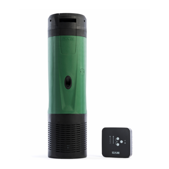
Summary of Contents for DAB DTron 3
- Page 1 اﻟﺸﻜﻞ Fig. - Fig. – Image - Abb. - Afb. – Fig. - Рис. - Obr. – Kuva – Fig. – Fig. – Εικ. – Şekil – Rys. – Ábra – Fig. – Фиг. - Fig.1 Fig.2 Fig.3 Fig.5...
- Page 2 Fig. 6 Fig. 7 Fig.8 Fig.9...
- Page 3 Fig.10 Fig.11 Fig. 12...
-
Page 4: Table Of Contents
ENGLISH CONTENTS WARNINGS ......................................12 RESPONSIBILITY ....................................13 GENERAL ....................................14 Applications ..................................14 Pumpable Liquids ................................14 Technical Data ................................... 14 INSTALLATION................................... 15 Mechanical Installation ..............................15 FIRST INSTALLATION ................................16 FUNCTION ....................................17 Pump start and stop conditions ............................17 Pump On –... -
Page 5: Responsibility
ENGLISH who lack experience or knowledge, on condition that they are under supervision or after they have received instructions concerning the safe use of the appliance and the understanding of the dangers involved. Children must not play with the appliance. Cleaning and maintenance intended to be carried out by the user must not be performed by children without supervision. -
Page 6: General
ENGLISH GENERAL Applications Multistage submerged pump with integrated electronics, ideal for use in rainwater systems and irrigation networks, for pumping water from tanks, cisterns, wells, lakes and for other domestic applications requiring high pressure. Thanks to their compact and handy shape, they are also used for particular applications as portable pumps for emergency situations such as for drawing water from tanks or rivers, draining swimming pools and fountains. -
Page 7: Installation
ENGLISH All technical data are marked on the technical label on the pump. The various items are explained below (Fig. 4): Pos. Description Description Revision Year Week Serial number Maximum liquid temperature Flow rate Maximum head Minimum head Insulation class Degree of protection Submersibility Rated voltage... -
Page 8: First Installation
ENGLISH It is advisable to use pipes having a minimum diameter of 1’’, to avoid the decrease of pump performance. The pump is suitable for vertical or horizontal installations. Connect a rigid or flexible pipe to the 1¼” delivery of the pump. The maximum submersibility of the pump depends on the length of the power cable: 12m (39.4 ft) in the case of a cable 15m (49.2 ft) long;... -
Page 9: Function
ENGLISH FUNCTION The electronics automatically control starting and stopping (ON/OFF) of the pump depending on the request for water. The electronics protect the pump from faults in the Non Return Valve (NRV) in the pump casing, which are generally caused by dirt or sand deposits. -
Page 10: Com Box
As described in the previous chapter, the DTRON3 and COM BOX in the package are already associated in the factory. If one of the two devices has to be replaced, it will be necessary to make a new association between COM BOX and DTRON 3, according to the... -
Page 11: Cleaning Storage Maintenance
ENGLISH Disconnect DTRON3 from the power mains Delete any previous associations on COM BOX (9.3.) Put COM BOX in the association phase (9.3.) Connect DTRON3 to the power mains Check the status of the PLC LED on COM BOX; if it is on with a steady light, the association has been successful. CLEANING STORAGE MAINTENANCE The pump does not require any maintenance. -
Page 12: Description Of Com Box Interface
ENGLISH DESCRIPTION OF COM BOX INTERFACE The interface of the DTRON3 pump is presented with the COM BOX unit, the panel of which is shown in the following figure: Figure 12: panel of the COM BOX device Description of operating mode COM BOX can operate in two modes, Monitor mode and SETUP mode. -
Page 13: Description Of Leds / Buttons
ENGLISH Description of LEDs / buttons See Figure 12 Function Explanation CUT-IN The lit LED indicates the CUT-IN value ON/OFF System status: on or off MOTOR STATUS Indicates whether or not the pump is operating ALARM Indicates that there is a general alarm MANUAL MODE Indicates manual operation Indicates correct communication between pump and COM... -
Page 14: Setup Mode
ENGLISH PUMP BLOCK function By simultaneously pressing and releasing the "+" and "-" buttons (fig 12, 1 - 2), the pump motor stops unconditionally and cannot start again until the "+" and "-" buttons (fig 12, 1 - 2) are pressed again simultaneously and released. This Inhibition also prevails over any motor start set in "MANUAL”...


Need help?
Do you have a question about the DTron 3 and is the answer not in the manual?
Questions and answers