
Subscribe to Our Youtube Channel
Related Manuals for Panduit Atlona AT-HDVS-200-TX


Summary of Contents for Panduit Atlona AT-HDVS-200-TX
- Page 1 Three-Input Switcher for HDMI and VGA with Ethernet-Enabled HDBaseT Output AT-HDVS-200-TX Atlona Manuals AT-HDVS-200-TX-PSK Switchers...
- Page 2 Version Information Version Release Date Notes Jan 2016 Initial release May 2017 Updated Jul 2017 New format Jul 2019 Moved API commands to separate document. AT-HDVS-200-TX / AT-HDVS-200-TX-PSK...
- Page 3 Welcome to Atlona! Thank you for purchasing this Atlona product. We hope you enjoy it and will take an extra few moments to register your new purchase. Registration only takes a few minutes and protects this product against theft or loss. In addition, you will receive notifications of product updates and firmware.
- Page 4 Atlona, Inc. (“Atlona”) Limited Product Warranty Coverage Atlona warrants its products will substantially perform to their published specifications and will be free from defects in materials and workmanship under normal use, conditions and service. Under its Limited Product Warranty, Atlona, at its sole discretion, will either: •...
- Page 5 Atlona, Inc. (“Atlona”) Limited Product Warranty • Damage, deterioration or malfunction resulting from the installation or removal of this product from any installation, any unauthorized tampering with this product, any repairs attempted by anyone unauthorized by Atlona to make such repairs, or any other cause which does not relate directly to a defect in materials and/or workmanship of this product.
- Page 6 Safety and Certification 9. Do not defeat the safety purpose of a polarized CAUTION or grounding-type plug. A polarized plug has two RISK OF ELECTRIC SHOCK blades with one wider than the other. A grounding DO NOT OPEN type plug has two blades and a third grounding CAUTION: TO REDUCT THE RISK OF prong.
-
Page 7: Table Of Contents
Table of Contents Introduction Features Package Contents Panel Description Installation RS-232 Connector Connection Instructions Connection Diagram IP Configuration Using the Front Panel Using Commands Using the Web GUI Basic Operation Defining the Front-Panel Buttons The Web GUI Introduction to the Web GUI Menu Bar Toggles Sliders... -
Page 8: Introduction
Introduction The Atlona AT-HDVS-200-TX is a 3×1 switcher and HDBaseT transmitter with two HDMI inputs and a VGA input with audio. Video signals up to 4K/UHD @ 60 Hz with 4:2:0 chroma subsampling, plus embedded audio, control, and Ethernet can be transmitted up to 330 feet (100 meters). The two-channel audio input can be assigned to any of the video inputs and embedded for HDBaseT transmission. -
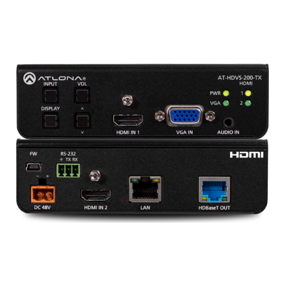
Page 9: Panel Description
Panel Description AT-HDVS-200-TX HDMI INPUT DISPLAY HDMI IN 1 VGA IN AUDIO IN AT-HDVS-200-TX RS-232 RS-232 HDMI INPUT DISPLAY HDMI IN 1 VGA IN AUDIO IN DC 48V HDMI IN 2 HDBaseT OUT Front Rear RS-232 RS-232 RS-232 HDMI IN 2 HDMI IN 2 HDBaseT OUT INPUT... -
Page 10: Installation
Installation RS-232 Connector The AT-HDVS-200-TX provides RS-232 control between an automation system and an RS-232 device. This step is optional. 1. Use wire strippers to remove a portion of the cable jacket. 2. Remove at least 3/16” (5 mm) from the insulation of the RX, TX, and GND wires. 3. -
Page 11: Connection Diagram
Installation AT-HDVS-200-TX-PSK Only 9. Connect the included power supply to the DC 48V port. Powering the AT-HDVS-200-TX-PSK will provide power to other HDBaseT receivers or projectors that require power. 10. Connect the power supply to an available AC outlet. Connection Diagram Audio Amplifier DI GI DI O... -
Page 12: Ip Configuration
Installation IP Configuration The AT-HDVS-200-TX is shipped with DHCP enabled. Once connected to a network, the DHCP server (if available), will automatically assign an IP address to the unit. Use an IP scanner, along with the MAC address on the bottom of the unit, to identify both the unit and its IP address on the network. -
Page 13: Using The Web Gui
Installation • Setting DHCP mode 1. Connect to the AT-HDVS-200-TX using RS-232 or Telnet. 2. At the command line, execute the IPDHCP command using the on argument, as shown. All characters are case-sensitive. IPDHCP on Once DHCP is enabled, the unit will be assigned an IP address by the DHCP server (if present). Using the Web GUI System page (page 30), in the web GUI, allows the AT-HDVS-200-TX to use either DHCP or static IP mode. -
Page 14: Basic Operation
Basic Operation Defining the Front-Panel Buttons The DISPLAY and VOL (up/dn) buttons, on the front panel, are user-defined. The factory-default setting of these buttons have no function. For example, pressing the DISPLAY button, will toggle the backlit LED on or off. This section covers how to assign a button to a function to control the display using CEC, RS-232, or IP protocols. - Page 15 Basic Operation 4. Locate the command sections (ON, OFF, Volume+, Volume-, and Mute). Each command will have a Set command field. 5. Click the Send Mode toggle switch to ASCII or HEX, depending upon the format of the command. 6. Enter the required command for each function, in the Set command fields. Consult the documentation of the display device to obtain the correct command string.
-
Page 16: The Web Gui
The Web GUI Introduction to the Web GUI The AT-HDVS-200-TX includes a built-in web GUI. Atlona recommends that the web GUI be used to set up the AT-HDVS-200-TX, as it provides intuitive management of all features. The AT-HDVS-200-TX is shipped with DHCP enabled. Once connected to a network, the DHCP server will automatically assign an IP address to the unit. -
Page 17: Menu Bar
The Web GUI 7. The Info page will be displayed. Menu Bar The dark-colored bar, near the top of the screen, is the menu bar. When the mouse is moved over each menu element, it will be highlighted in light orange. Once the desired menu element is highlighted, click the left mouse button to access the settings within the menu. -
Page 18: Toggles
The Web GUI Toggles Several settings within the Web GUI use toggles, which enable, disable, or assign one of two settings. Generally, when the toggle is blue, it means that the feature is enabled or ON. If a feature is disabled, then the toggle will appear gray and be labeled as OFF. -
Page 19: Info Page
The Web GUI Info page After logging in, the Info page will be displayed. The Info page provides basic information about the receiver, including the model name, software version, input video timing, and the device being using as the transmitter. Receiver Model Name The model SKU of this product. -
Page 20: Video Page
The Web GUI Video page Input Selection Click this drop-down list to select the desired input. VGA Adjust In most situations, adjustment of the VGA signal should not necessary. However, if the VGA signal does not appear correctly, click the Adjust button to automatically correct the clock and phase. Auto Switch Three controls are available under the Auto Switch feature. -
Page 21: Audio Page
The Web GUI Audio page HDMI Audio These drop-down lists are only available when the system is in kit mode. Refer to Kit Mode (page 33) for more information. Audio Freerun Status Audio can be passed, without the presence of a video signal. To enable this functionality, click the Audio Freerun Status toggle to the ON position. - Page 22 The Web GUI L/R Audio Click this toggle to the OFF position to mute only the analog audio. Output Click and drag this slider bar to adjust the output audio volume. Range: -80 to 0. Output Bass Click and drag this slider bar to adjust the bass of the audio output. Range: -12 to 15. Output Treble Click and drag this slider bar to adjust the treble of the audio output.
-
Page 23: Display Page
The Web GUI Display page CEC Command Click the ON button to send the power-on command to the display device. Click the OFF button to toggle the power state to off. Consumer Electronics Control (CEC): Atlona has confirmed proper CEC functionality with several current models of Samsung, Panasonic, and Sony displays. -
Page 24: System Settings
The Web GUI System Settings Display Auto Power On Sends the command to power-on the display when an A/V signal is detected. Click the toggle to enable or disable this feature. Otherwise, set to DISABLED. Display Auto Power Off Sends the command to power-off the display when an A/V signal is no longer present. Click the toggle to enable or disable this feature. -
Page 25: Tcp/Ip Settings Of Controlled Devices
The Web GUI Display Mode Click this drop-down list to select the display mode. Setting Description DispSW AVon Display switches on/off, source audio/video signal always on. DispSW AVSW Display switches on/off, source audio/video signal switches on/off. AV SW Display is always on, source audio/video signal switches on/off Volume / Mute Click this drop-down list to select the control method for volume and muting. -
Page 26: Rs-232 / Ip Commands
The Web GUI RS-232 / IP Commands Send Mode Sets the type of commands that are sent to the display, either ASCII or Hex. On/Off/Volume+/Volume-/Mute • Set command Enter the command in this field. • Feedback Enter the feedback string in this field. •... -
Page 27: Rs-232 Page
The Web GUI RS-232 page Zone When the AT-HDVS-200-TX is connected to the AT-HDVS-200-RX, the system is placed in kit mode. In this mode, the drop-down list boxes will be disabled and the HDBaseT baud rate will be locked at 115200. If the AT-HDVS-200-TX is connected to another HDBaseT device, such as the AT-UHD-CLSO-824, each of these drop-down list boxes can be set to the baud rate of the HDBaseT RS-232 settings on the corresponding device. -
Page 28: Edid Page
The Web GUI EDID page Perfer Timing (HDMI) Click this drop-down list to select the preferred timing for the HDMI signal. Prefer Timing (VGA) Click this drop-down list to select the preferred timing for the VGA signal. Input1 HDCP / Input2 HDCP Provides control over the transmission of HDCP content for the HDMI IN 1 and HDMI IN 2 ports. -
Page 29: Config Page
The Web GUI Config page Old Username This field cannot be changed. “root” is the administrator user. Old Password Enter the current password for the “root” username in this field. The default password is “Atlona”. New Username This field cannot be changed. Save Click this button to save all changes. -
Page 30: System Page
The Web GUI System page IP Mode Click this toggle to set the IP mode of the AT-HDVS-200-TX. By default, the AT-HDVS-200-TX is set to DHCP mode. Available settings: STATIC IP, DHCP. Enter the IP address of the AT-HDVS-200-TX in this field. This field will only be available if IP Mode is set to STATIC IP. - Page 31 The Web GUI Reset to Default Click the Factory Default button to set the AT-HDVS-200-TX to factory-default settings. Firmware Update Click the Choose File button to select the firmware file, when upgrading the firmware on the AT-HDVS-200-TX. Once the firmware file is selected, click the Update button. Refer to Updating the Firmware (page 37) for more information.
-
Page 32: Hdbt Page
The Web GUI HDBT page HDBaseT Channel The AT-HDVS-200-TX has only a single HDBaseT output. Therefore, this drop-down list is disabled. Start / Stop Click the Start button to being the HDBaseT testing. During testing, the button text will change to “Stop”. Click the Stop button to halt the HDBaseT testing process. -
Page 33: Kit Mode
The Web GUI Kit Mode If the AT-HDVS-200-TX is connected to the AT-HDVS-200-TX, the system will be placed in kit mode. This section covers features only available in kit mode. Note that the text “GENERAL” has been replaced with the name of receiver (AT-HDVS-200-TX). - Page 34 The Web GUI Output Resolution Click the Output Resolution drop-down list and select the desired resolution. The default resolution is 720p. Output Resolutions 800x600@60 1024x768@60 1280x800@60 1280x1024@60 1366x768@60 1400x1050@60 1600x900@60RB 1600x1200@60 1680x1050@60 1920x1200@60RB 720p25 720p29.97 720p30 720p50 720p59.94 720p60 1080i50 1080i59.94 1080i60 1080p23.98...
-
Page 35: Audio
The Web GUI Audio HDMI Audio (mute) HDMI Audio (audio select) L/R Audio (mute) HDMI Audio Click the drop-down list for HDMI 1 and HDMI 2 to select the input audio source used by each HDMI input. Setting Description Auto Automatically detects the audio source. - Page 36 The Web GUI RS-232 RX RS-232 Zone 1 RX RS-232 Zone 1 Each of these drop-down lists refer to the setting for the RS-232 1 port on the receiver. Click the Save button to save the settings. Setting Description Baud rate Sets the baud rate.
-
Page 37: Appendix
Appendix Updating the Firmware Updating the firmware can be completed using either the USB interface or the web GUI. Atlona recommends using the web GUI for updating the firmware. However, if a network connection is not available, the AT-HDVS-200-TX firmware can be updated using a USB-A to USB mini-B cable Using the Web GUI Requirements •... -
Page 38: Using Usb
Appendix 6. The following message box will be displayed. 7. Click the OK button to begin the firmware update process. Click the Cancel button to cancel the process. 8. After the firmware update process is complete, the Login screen will be displayed. Using USB Requirements •... - Page 39 Appendix 3. Press and hold the INPUT button, on the front panel, while connecting power to the AT-HDVS-200-TX. 4. The USB UPDATE folder will be displayed. If this folder is not displayed, automatically, select the USB UPDATE drive from Windows Explorer. 7.
-
Page 40: Default Settings
Appendix Default Settings The following tables list the factory-default settings for the AT-HDVS-200-TX. Feature Settings Video Input Selection HDMI 1 Aspect Full Auto Switch mode Fallback Port Previous Fallback Time (Sec) Audio HDMI 1 Auto HDMI 2 Auto Audio Freerun Status Mute Output Volume Output Bass... -
Page 41: Specifications
Appendix Specifications Video HD/SD 4096×2160@24/25/30/50*/60Hz*, 3840×2160@24/25/30/50*/60Hz*, 2048x1080p, 1080p@23.98/24/25/29.97/30/50/59.94/60Hz, 1080i@50/59.94/60Hz, 720p@50/59.94/60Hz, 576p, 576i, 480p, 480i VESA 2560×2048, 2560×1600, 2048×1536, 1920×1200, 1680×1050, 1600×1200, 1600×900, 1440×900, 1400×1050, 1366×768, 1360×768, 1280×1024, 1280×800 1280×768, 1152×768, 1024×768, 800×600, 640×480 Color Space YUV, RGB Chroma Subsampling 4:4:4, 4:2:2, 4:2:0* Color Depth 8-bit, 10-bit, 12-bit Audio... - Page 42 Appendix Power Consumption 12 W; 30 W (when paired) Dimensions Inches Millimeters H x W x D 1.5 x 5 x 4.02 38 x 127 x 102 Weight Pounds Kilograms Device 0.64 0.29 Certification Unit CE, FCC AT-HDVS-200-TX / AT-HDVS-200-TX-PSK...
-
Page 43: Index
Index adjusting 21, 22 Aspect ratio Installation Audio IP configuration passing only audio using commands Users using the front panel adding using the web GUI editing primary user name Bass removing adjusting 21, 22 Brightness 34, 36 Kit mode signal adjustment Netmask compatibility 3, 23... - Page 44 Toll free US International atlona.com 877.536.3976 41.43.508.4321 • • © 2020 Atlona Inc. All rights reserved. “Atlona” and the Atlona logo are registered trademarks of Atlona Inc. All other brand names and trademarks or registered trademarks are the property of their respective owners. Pricing, specifications and availability subject to change without notice.
Need help?
Do you have a question about the Atlona AT-HDVS-200-TX and is the answer not in the manual?
Questions and answers