Table of Contents
Advertisement
Quick Links
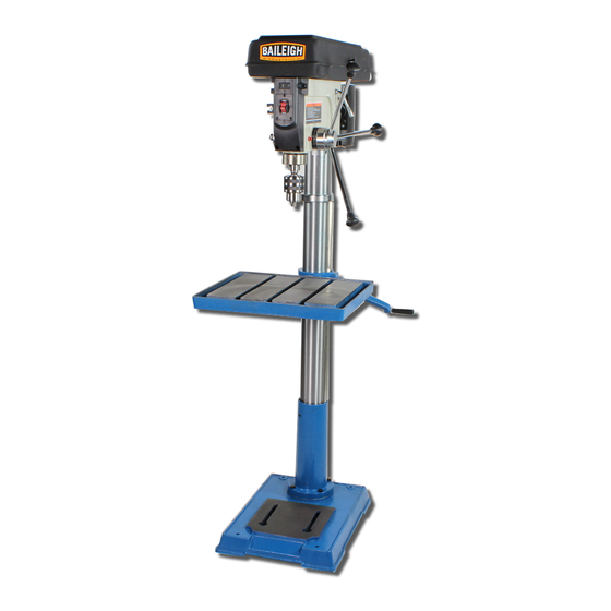
MODEL: DP-1512B AND DP-1512F
REPRODUCTION OF THIS MANUAL IN ANY FORM WITHOUT WRITTEN APPROVAL OF BAILEIGH INDUSTRIAL, INC.
IS PROHIBITED. Baileigh Industrial, Inc. does not assume and hereby disclaims any liability for any damage or loss
caused by an omission or error in this Operator's Manual, resulting from accident, negligence, or other occurence.
OPERATOR'S
DRILL PRESS
Baileigh Industrial, Inc.
P.O. Box 531
Manitowoc, WI 54221-0531
Phone: 920.684.4990
Fax: 920.684.3944
sales@baileighindustrial.com
© 2012 Baileigh Industrial, Inc.
MANUAL
Rev. 8/2012
Advertisement
Table of Contents

Related Manuals for Baileigh DP-1512B


Summary of Contents for Baileigh DP-1512B
-
Page 1: Drill Press
REPRODUCTION OF THIS MANUAL IN ANY FORM WITHOUT WRITTEN APPROVAL OF BAILEIGH INDUSTRIAL, INC. IS PROHIBITED. Baileigh Industrial, Inc. does not assume and hereby disclaims any liability for any damage or loss caused by an omission or error in this Operator’s Manual, resulting from accident, negligence, or other occurence. -
Page 2: Table Of Contents
Table of Contents THANK YOU & WARRANTY ..................1 INTRODUCTION ......................3 GENERAL NOTES......................3 SAFETY INSTRUCTIONS ....................4 SAFETY PRECAUTIONS ....................6 TECHNICAL SPECIFICATIONS ..................9 TECHNICAL SUPPORT ....................9 UNPACKING AND CHECKING CONTENTS ..............10 Bagged and Boxed Parts ................... 11 TRANSPORTING AND LIFTING .................. -
Page 3: Thank You & Warranty
THANK YOU & WARRANTY Thank you for your purchase of a machine from Baileigh Industrial. We hope that you find it productive and useful to you for a long time to come. Inspection & Acceptance. Buyer shall inspect all Goods within ten (10) days after receipt thereof. Buyer’s payment shall constitute final acceptance of the Goods and shall act as a waiver of the Buyer’s rights to inspect or... - Page 4 Baileigh Industrial makes every effort to ensure that our posted specifications, images, pricing and product availability are as correct and timely as possible. We apologize for any discrepancies that may occur. Baileigh Industrial reserves the right to make any and all changes deemed necessary in the course of business including but not limited to pricing, product specifications, quantities, and product availability.
-
Page 5: Introduction
After receiving your equipment remove the protective container. Do a complete visual inspection, and if damage is noted, photograph it for insurance claims and contact your carrier at once, requesting inspection. Also contact Baileigh Industrial and inform them of the unexpected occurrence. Temporarily suspend installation. -
Page 6: Safety Instructions
IMPORTANT PLEASE READ THIS OPERATORS MANUAL CAREFULLY It contains important safety information, instructions, and necessary operating procedures. The continual observance of these procedures will help increase your production and extend the life of the equipment. SAFETY INSTRUCTIONS LEARN TO RECOGNIZE SAFETY INFORMATION This is the safety alert symbol. - Page 7 PROTECT EYES Wear safety glasses or suitable eye protection when working on or around machinery. BEWARE OF PIERCING POINTS Keep hands and fingers away from the rotating drill bit. ENTANGLEMENT HAZARD – ROTATING SHAFT Contain long hair, DO NOT wear jewelry or loose fitting clothing, and DO NOT wear gloves.
-
Page 8: Safety Precautions
SAFETY PRECAUTIONS Wood working can be dangerous if safe and proper operating procedures are not followed. As with all machinery, there are certain hazards involved with the operation of the product. Using the machine with respect and caution will considerably lessen the possibility of personal injury. However, if normal safety precautions are overlooked or ignored, personal injury to the operator may result. - Page 9 SAFETY PRECAUTIONS (cont.) 12. Stay alert. Watch what you are doing and use common sense. DO NOT operate any tool or machine when you are tired. 13. Drill Operation. Never start the drill press with the drill bit pressed against the piece part. Feed the drill bit slowly and evenly into the piece part.
- Page 10 SAFETY PRECAUTIONS (cont.) 28. Make sure machine is disconnected from power supply while motor is being mounted, connected or reconnected. WARNING: The dust generated by certain woods and wood products can be injurious to your health. Always operate machinery in well ventilated areas and provide for proper dust removal.
-
Page 11: Technical Specifications
TECHNICAL SPECIFICATIONS Description DP-1512B DP-1512F Type Belt drive Belt drive Motor 3/4hp (.55kw) / 1 ph 3/4hp (.55kw) / 1 ph Power Supply 110V 60hz 110V 60hz Spindle speed 16 Position : 220~3600rpm 16 Position : 220~3600rpm Number of Speeds... -
Page 12: Unpacking And Checking Contents
UNPACKING AND CHECKING CONTENTS Separate all parts from packaging materials and check each Item make sure all items are accounted for before discarding any packing material. Item Description Table Column Support Arm Owner's Manual Motor Bag of Loose Parts Base Head Assembly Box of Loose Parts... -
Page 13: Bagged And Boxed Parts
Bagged and Boxed Parts... -
Page 14: Transporting And Lifting
TRANSPORTING AND LIFTING CAUTION: Lifting and carrying operations should be carried out by skilled workers, such as a truck operator, crane operator, etc. If a crane is used to lift the machine, attach the lifting chain carefully, making sure the machine is well balanced. Choose a location that will keep the machine free from vibration and dust from other machinery. -
Page 15: Cleaning
Cleaning Your machine may be shipped with a rustproof waxy oil coating and grease on the exposed unpainted metal surfaces. To remove this protective coating, use a degreaser or solvent cleaner. For a more thorough cleaning, some parts will occasionally have to be removed. DO NOT USE acetone or brake cleaner as they may damage painted surfaces. -
Page 16: Getting To Know Your Machine
GETTING TO KNOW YOUR MACHINE... -
Page 17: Assembly
ASSEMBLY Read and understand all assembly instructions before attempting assembly! Failure to comply may cause serious injury! Base Column with Support M10 x 1.5-40 Screw (4) Head Assembly Table Feed Handle Clamp – Column Lock Crank 1. Provide a location for assembly that provide the clearance needed to work around the machine, lifting... -
Page 18: Chuck And Arbor Installation
8. Using a second person a suitable and secure lifting devise, carefully lift the head assembly (4) above and onto the column top and slide it down into position. The head assembly is heavy! Use care when lifting onto the column! WARNING: Change the radial position of the drill head only if the drill press base is secured to the floor. -
Page 19: Adjustment
ADJUSTMENT Depth Stop Adjustment To drill a hole or holes at a preset depth, use the depth stop: 1. Using a scrap piece of wood of the same thickness, mark the side of the wood at the depth the bit will drill into the workpiece. 2. -
Page 20: Operating Precautions
OPERATING PRECAUTIONS The following operating and safety precautions must be observed in order to avoid harm to the operator or damage to the drill press. 1. Safety is the responsibility of the user/purchaser since conditions differ between jobs. Use and enforce safety procedures at each operation location and provide for any changes in conditions to provide maximum safety. -
Page 21: Drilling Recommendations
DRILLING RECOMMENDATIONS Speeds for Drilling The speed of a drill is usually measured in terms of the rate at which the outer periphery of the tool moves in relation to the work being drilled. The common term for this is Surface Feet per Minute (SFM). -
Page 22: Speeds For High Speed Steel Drills
Speeds for High Speed Steel Drills Material Speed In SFM Alloy Steel-· 300 to 400 Brinell 20 - 30 Stainless Steel 30 - 40 Automotive Steel Forgings 40- 50 Tool Steel, 1.2C 50 - 60 Steel, .4C to .5C 70 - 80 Mild Machinery Steel, .2C to .3C 80-110 Hard Chilled Cast Iron... -
Page 23: Lubrication And Maintenance
LUBRICATION AND MAINTENANCE WARNING: Make sure the electrical disconnect is OFF before working on the machine. Maintenance should be performed on a regular basis by qualified personnel. Always follow proper safety precautions when working on or around any machinery. Daily Maintenance ... -
Page 24: Wiring Diagram
WIRING DIAGRAM... -
Page 25: Base, Column, Table Parts
BASE, COLUMN, TABLE PARTS Item Description Item Description Screw-Hex Socket Set M6x1.0-10 Support Column Collar-Rack Screw-Hex HD M10x1.5-40 Gear-Helical Screw-Hex Socket Set M10x1.5-12 Crank 14 Tube Column Table Rack Clamp-Table Clamp-Column Screw-Hex HD M16x20-35 Support-Table w/indicator Arm-Table w/Scale Worm-Elevation Base Pin-Gear... -
Page 26: Quill And Chuck Parts
QUILL and CHUCK PARTS Item Description Item Description Nut-lock Key-Chuck Ring-locking Chuck Washer Arbor Bearing-Ball 17mm Key-Drift Washer-Rubber Spindle Tube-Quill Bearing-Ball... -
Page 27: Drive Train Parts
DRIVE TRAIN PARTS Item Description Item Description Ring-Retaining Pulley-Motor Bearing Ball 25mm Knob Spacer-Bearing Screw-Pan HD M5x0.8-12 Belt-'V' M24 Pivot-Idler Nut-Pulley Pulley-Center Pulley-Spindle Bearing Ball 15mm Insert-Pulley Belt-'V' M26 Guard-Pulley w/Labels Washer Foam Screw-RD HD Washer M6x1 .0-16 Lock Washer Ext.M6 Screw-Set M10x1.5-12... -
Page 28: Motor And Head Assembly Parts
MOTOR and HEAD ASSEMBLY PARTS... -
Page 29: Motor And Head Assembly Parts List
Motor and Head Assembly Parts List Item Description Item Description Knob-Motor Adjusting Retainer-spring Screw-Socket Set M10 x 1.5-12 Spring-Torsion Handle-Belt Tension Cap-Spring Pin-stop Nut-Hex M12 x 1.5-8 Ring-Depth Stop w/Scale Head w/Pointer and Trim Lock-Depth Screw Socket-Bulb Assembly 60W max. Tie-Wire Guide Scale Cord-Power w/Plug... -
Page 30: Troubleshooting
TROUBLESHOOTING WARNING: Make sure the electrical disconnect is OFF before working on the machine. FAULT PROBABLE CAUSE REMEDY 1. Adjust tension. 1. Incorrect belt tension. 2. Lubricate spindle. 2. Dry Spindle. 3. Checking tightness of retaining Noisy Operation 3. Loose spindle pulley. nut on pulley, and tighten if 4. - Page 31 NOTES...
- Page 32 , WI 54220 UFEK RIVE ANITOWOC : 920. 684. 4990 F : 920. 684. 3944 HONE BAILEIGHINDUSTRIAL BAILEIGH INDUSTRIAL, INC. 1455 S. C , CA 91761 AMPUS VENUE NTARIO : 920. 684. 4990 F : 920. 684. 3944 HONE BAILEIGH INDUSTRIAL LTD. U...
Need help?
Do you have a question about the DP-1512B and is the answer not in the manual?
Questions and answers