Table of Contents
Advertisement
Quick Links
OPERATOR'S
MANUAL
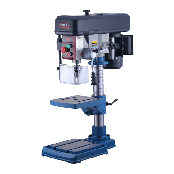
MULTI-SPEED BELT DRIVE DRILL PRESS
MODEL: DP-3814B
Baileigh Industrial Holdings LLC,
P.O. Box 531
Manitowoc, WI 54221-0531
Phone: 920.684.4990
Fax: 920.684.3944
sales@baileigh.com
REPRODUCTION OF THIS MANUAL IN ANY FORM WITHOUT WRITTEN APPROVAL OF BAILEIGH INDUSTRIAL
HOLDINGS LLC, IS PROHIBITED. Baileigh Industrial Holdings LLC, does not assume and hereby disclaims any
liability for any damage or loss caused by an omission or error in this Operator's Manual, resulting from accident,
negligence, or other occurrence.
Rev. 04/2020
© 2020 Baileigh Industrial Holdings LLC
Advertisement
Table of Contents

Subscribe to Our Youtube Channel
Related Manuals for Baileigh DP-3814B


Summary of Contents for Baileigh DP-3814B
- Page 1 REPRODUCTION OF THIS MANUAL IN ANY FORM WITHOUT WRITTEN APPROVAL OF BAILEIGH INDUSTRIAL HOLDINGS LLC, IS PROHIBITED. Baileigh Industrial Holdings LLC, does not assume and hereby disclaims any liability for any damage or loss caused by an omission or error in this Operator’s Manual, resulting from accident, negligence, or other occurrence.
-
Page 2: Table Of Contents
Table of Contents THANK YOU & WARRANTY ..................1 INTRODUCTION ......................3 GENERAL NOTES ......................3 SAFETY INSTRUCTIONS ....................4 SAFETY PRECAUTIONS ....................6 Dear Valued Customer: ....................6 TECHNICAL SPECIFICATIONS ..................9 TECHNICAL SUPPORT ....................10 UNPACKING AND CHECKING CONTENTS ..............11 Cleaning ........................ -
Page 3: Thank You & Warranty
THANK YOU & WARRANTY Thank you for your purchase of a machine from Baileigh Industrial Holdings LLC. We hope that you find it productive and useful to you for a long time to come. Inspection & Acceptance. Buyer shall inspect all Goods within ten (10) days after receipt thereof. Buyer’s payment shall constitute final acceptance of the Goods and shall act as a waiver of the Buyer’s rights to inspect or... - Page 4 We apologize for any discrepancies that may occur. Baileigh Industrial Holdings LLC reserves the right to make any and all changes deemed necessary in the course of business including but not limited to pricing, product specifications, quantities, and product availability.
-
Page 5: Introduction
INTRODUCTION The quality and reliability of the components assembled on a Baileigh Industrial Holdings LLC machine guarantee near perfect functioning, free from problems, even under the most demanding working conditions. However, if a situation arises, refer to the manual first. If a solution cannot be found, contact the distributor where you purchased our product. -
Page 6: Safety Instructions
IMPORTANT PLEASE READ THIS OPERATORS MANUAL CAREFULLY It contains important safety information, instructions, and necessary operating procedures. The continual observance of these procedures will help increase your production and extend the life of the equipment. SAFETY INSTRUCTIONS LEARN TO RECOGNIZE SAFETY INFORMATION This is the safety alert symbol. - Page 7 SAVE THESE INSTRUCTIONS. Refer to them often and use them to instruct others. PROTECT EYES Wear safety glasses or suitable eye protection when working on or around machinery. PROTECT AGAINST NOISE Prolonged exposure to loud noise can cause impairment or loss of hearing.
-
Page 8: Safety Precautions
• All Baileigh woodworking machines should be used only for their intended use. • Baileigh does not recommend or endorse making any modifications or alterations to a Baileigh machine. Modifications or alterations to a machine may pose a substantial risk of injury to the operator or others and may do substantial damage to the machine. - Page 9 1. FOR YOUR OWN SAFETY, READ INSTRUCTION MANUAL BEFORE OPERATING THE MACHINE. Learn the machine’s application and limitations as well as the specific hazards. 2. Only trained and qualified personnel can operate this machine. 3. Make sure guards are in place and in proper working order before operating machinery.
- Page 10 18. Be sure all equipment is properly installed and grounded according to national, state, and local codes. 19. Inspect power and control cables periodically. Replace if damaged or bare wires are exposed. Bare wiring can kill! 20. Keep visitors a safe distance from the work area. 21.
-
Page 11: Technical Specifications
TECHNICAL SPECIFICATIONS 0.625” (16mm) Drilling Capacity B16, 0.039” – 0.625” (1 – 16mm) Chuck 3.34” (85mm) Spindle Travel Spindle Taper 1.85” (47mm) Quill Diameter 14” (360mm) Swing 0” (0mm) Min. Distance Spindle to Table 13.38” (340mm) Max. Distance Spindle to Table 21.65”... -
Page 12: Technical Support
(other than die sets and blades). For specific application needs or future machine purchases contact the Sales Department at: sales@baileigh.com, Phone: 920.684.4990, or Fax: 920.684.3944. Note: The photos and illustrations used in this manual are representative only and may not depict the actual color, labeling or accessories and may be intended to illustrate technique only. -
Page 13: Unpacking And Checking Contents
UNPACKING AND CHECKING CONTENTS Your Baileigh machine is shipped complete. Separate all parts from the packing material and check each item carefully. Make certain all items are accounted for before discarding any packing material. WARNING: SUFFOCATION HAZARD! Immediately discard any plastic bags and packing materials to eliminate choking and suffocation hazards to children and animals. -
Page 14: Transporting And Lifting
TRANSPORTING AND LIFTING NOTICE: Lifting and carrying operations should be carried out by skilled workers, such as a truck operator, crane operator, etc. If a crane is used to lift the machine, attach the lifting chain carefully, making sure the machine is well balanced. Follow these guidelines when lifting with truck or trolley: •... -
Page 15: Installation
INSTALLATION IMPORTANT: Consider the following when looking for a suitable location to place the machine: • Overall weight of the machine. • Weight of material being processed. • Sizes of material to be processed through the machine. • Space needed for auxiliary stands, work tables, or other machinery. •... -
Page 16: Anchoring The Machine
Anchoring the Machine WARNING: Before operating the Baileigh Drill Press make sure it is securely bolted to a bench which is in turn secured to the floor to prevent tip over. If the drill press tips over on you, it could cause severe injury or death. -
Page 17: Getting To Know Your Machine
GETTING TO KNOW YOUR MACHINE... - Page 18 Head to Column Clamping Bolt. Allows head to pivot on the Column. WARNING: Before operating the Baileigh Drill Press make sure it is firmly secured to a bench. If it tips over on you, it could cause severe injury or death.
-
Page 19: Assembly And Set Up
ASSEMBLY AND SET UP WARNING: For your own safety, DO NOT connect the machine to the power source until the machine is completely assembled and you read and understand the entire instruction manual. Two Person Lift. A lifting device will be needed, and an assistant is highly recommended. - Page 20 CAUTION: Before operating the drill each day, verify that the head is secured to the column. Failure to ensure that the head is secure to the column may allow the head to twist unexpectedly during operation causing damage and or injury. 9.
-
Page 21: Electrical
ELECTRICAL CAUTION: HAVE ELECTRICAL UTILITIES CONNECTED TO MACHINE BY A CERTIFIED ELECTRICIAN! Check if the available power supply is the same as listed on the machine nameplate. WARNING: Make sure the grounding wire (green) is properly connected to avoid electric shock. DO NOT switch the position of the green grounding wire if any electrical plug wires are switched during hookup. - Page 22 • Improper connection of the equipment-grounding conductor can result in risk of electric shock. The conductor with insulation having an outer surface that is green with or without yellow stripes is the equipment-grounding conductor. If repair or replacement of the electric cord or plug is necessary, do not connect the equipment-grounding conductor to a live terminal.
-
Page 23: Electrical Schematic
ELECTRICAL SCHEMATIC Electrical Parts List Item Description Type Specification SQ3 Belt Break Proximity Switch LJC1-3/24, CHIIB 1.2W, 50mA SQ4 Chuck Shield Micro Switch KW7, LEMA, CE 125/250V 8A Start Switch LA115-A5-10BN, GQELE, CE Ui:600V, Ith:10A Stop Switch LA115-A5-01BN, GQELE, CE Ui:600V, Ith:10A Emergency Stop Switch LA115-A5-01ZS, GQELE, CE... -
Page 24: Operating Adjustments
OPERATING ADJUSTMENTS Belt / Speed Change 1. Disconnect the drill from the power supply. 2. Remove the lock knob and washer from the top of the belt cover. 3. Remove the belt cover 4. Use the chart on the face of the control panel to determine the rpm desired. -
Page 25: Drill Head And Worktable Adjustment
Drill Head and Worktable Adjustment This drill press design allows for the head and the worktable to be adjusted and rotated as needed to provide for a wide variety of drilling options. NOTICE: Use care to maintain load balance when rotating the table. When applying downward pressure during the drilling process, a poorly secured work piece may come loose and fall or rotate causing material or equipment damage. - Page 26 Worktable Adjustment The worktable may be adjusted three ways; Elevation, rotating around the column, and tilting. Note: Always remove all material, tools and vises before adjusting the worktable. Elevation and Rotation 1. Support the worktable and loosen the clamping bolt (A). 2.
-
Page 27: Depth Stop
Depth Stop This drill press comes with a depth stop adjustment for use when drilling. 1. Loosen the depth collar lock knob (A). 2. Secure the material you will be drilling onto the drill press table. 3. With the desired bit installed, lower the spindle until the tip of the bit just touches the material you will be drilling. -
Page 28: Operating Precautions
5. The stop block (B) can be set at different positions by loosening the lock bolt (B also), sliding the guard and shaft assembly upward, and then tightening the lock bolt to hold the guard at that position. OPERATING PRECAUTIONS The following operating and safety precautions must be observed in order to avoid harm to the operator or damage to the drill press. -
Page 29: Indication Of Extreme Speeds And Feeds
5. Verify that the chuck is clear of any entanglements and start the drill. 6. Selects the appropriate spindle speed for the workpiece and drill bit. 7. Wears safety glasses or a face shield. 8. Starts the machine. 9. Use the feed handle to feed the drill into the material. Use a smooth steady motion with enough force to allow the drill to cut. -
Page 30: Lubrication And Maintenance
LUBRICATION AND MAINTENANCE WARNING: Make sure the electrical disconnect is OFF before working on the machine. Maintenance should be performed on a regular basis by qualified personnel. Always follow proper safety precautions when working on or around any machinery. Daily Maintenance •... -
Page 31: Greasing The Machine
• Inspect belt regularly for tension and wear. Check pulleys to ensure that they are properly aligned. Note: Proper maintenance can increase the life expectancy of your machine. Greasing the Machine • Lubricate the spline of the spindle and the teeth of the rack with a #2 grease. •... - Page 32 drill and material being drilled. Use correct cutting fluid. No cutting fluid or improper cutting fluid. Drill dull. Sharpen drill. Check that all T-slot hold-downs are tight, Lack of rigidity in hold-down and that table-lock and drill head bolts are method.
-
Page 33: Parts Diagram
PARTS DIAGRAM... -
Page 34: Parts List
Parts List Item Part No. Description Size Qty. S1401001 Base M12GB6177D1Z M12X60GB35Z Bolt M12X60 M16GB6170B S1401004 Table Support S1401014 Table S1606001 Tilt Scale M12X40GB5783B Hex Cap Screw M12X40 WSH12GB96D1B Washer S1601016 Double End Bolt WSH16GB96D1Z Flat Washer RVT2D5X5GB827C Rivet M2.5X5 S1401012 Hex Socket Cap Screw WSH12GB848B... - Page 35 Item Part No. Description Size Qty. S1604005 Handle S1604011 Grip S1604013 Ring S1604012 Bolt PIN4X16GB879D1B 4X16mm S1404002 Pinion Shaft PIN8X25GB879D1B 8X25mm M5X6GB77B Set screw M5X6 S1609009 Indicator M4X8GB818B Cross Pan Head Screw M4X8 M5X10GB818Z Cross Pan Head Screw M5X10 S1604007 Spring Cover S1604008 Collar...
- Page 36 Item Part No. Description Size Qty. S1605003 Plate S1605004 Hinge M4GB6170B S1405009 Shaft S1606014 Proximity Switch Seat LJC1-3-24 Proximity Switch M4X16GB818B Cross Pan Head Screw M4X16 S1605008 Locking Button S1402010 Cover DZ07B, 110~120V Relay M4X10GB818B Cross recess pan head screw M4X10 S1409005 Block M8X20GB70D1B...
- Page 37 Item Part No. Description Size Qty. S1609008 Shifter Bolt M6X40GB819D1Z Screw M6X40 M6X12GB70D1B Hex Socket Cap Screw M6X12 WSH6GB96D1B Flat Washer S1401003 Column S1401015-01 Column base S1401007 Elevation Collar 420J Poly V-belt 420J Adjusting Rod DP-ACC-01 Chuck Key (not shown) DP-ACC-03 L-Hex Wrench (not shown) 2.5mm...
- Page 38 NOTES...
- Page 39 NOTES...
- Page 40 BAILEIGH INDUSTRIAL HOLDINGS LLC 1625 D , WI 54220 UFEK RIVE ANITOWOC : 920. 684. 4990 F : 920. 684. 3944 HONE www.baileigh.com BAILEIGH INDUSTRIAL HOLDINGS LTD. U WIFT OINT WIFT ALLEY NDUSTRIAL STATE UGBY , CV21 1QH U IDLANDS...
Need help?
Do you have a question about the DP-3814B and is the answer not in the manual?
Questions and answers