
Subscribe to Our Youtube Channel
Related Manuals for Siemens SITRANS F US SONOFLO


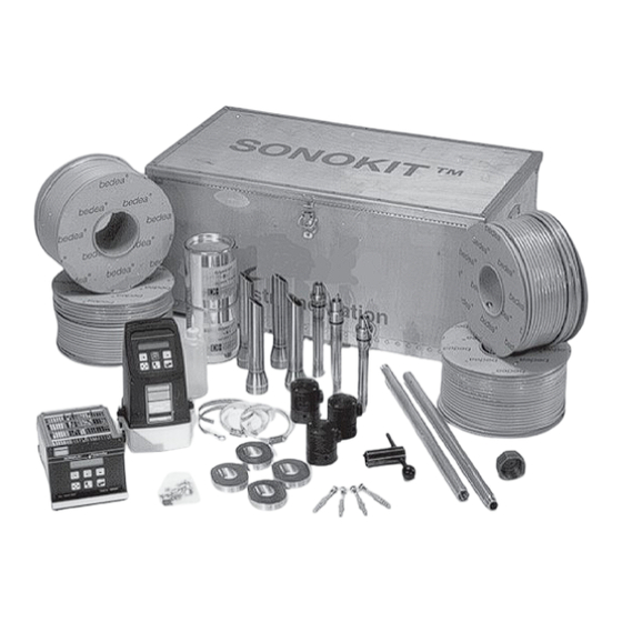
Summary of Contents for Siemens SITRANS F US SONOFLO
- Page 1 Handbook ® ® ® ® ® SITRANS F US SONOFLO Ultrasonic Flowmeter Type SONOKIT 1-track DN 100 - DN 4000 Order no.: FDK:521H0553 *085R9381* SFIDK.PS.029.V3.02...
-
Page 2: Table Of Contents
® ® ® ® ® SITRANS F US SONOFLO Contents Contents Introduction Location ............................3 Choice of measuring site Direction of flow ..........................4 Full pipes ............................4 Installation in horizontal pipes ......................4 Measuring liquids containing abrasive or other particles ..............5 Inlet and outlet conditions ....................... -
Page 3: Introduction
This manual only describes the SONOKIT installation in empty unpressurized pipes. When installing SONOKIT in pressurized pipes (hot tapping), please contact Siemens Flow Instruments for further instructions. SONOKIT is designed for measuring the flow velocity of liquids in full pipes. Satisfactory function of the ultrasonic flowmeter depends on a low attenuation of the medium and a well-defined and stable flow profile. -
Page 4: Choice Of Measuring Site
® ® ® ® ® SITRANS F US SONOFLO 2. Choice of measuring site Direction of flow Double arrow marked with "+" and "−" on the sensor. + indicates direction of flow when the electrical connections correspond to the ones described in the manual. -
Page 5: Measuring Liquids Containing Abrasive Or Other Particles
® ® ® ® ® 2. Choice of measuring site SITRANS F US SONOFLO Measuring liquids contain- The sensor should be mounted in vertical or ing abrasive or other inclined pipe position to minimize wear. particles Inlet and outlet conditions To maximize performance inlet and outlet must be straight. -
Page 6: Installation Of Transducer Type Sono 3200
® ® ® ® ® SITRANS F US SONOFLO 2. Choice of measuring site Installation of transducer The transducer type SONO 3200 is used together with the mounting kit type SONOKIT. type SONO 3200 O-ring type: The transducer has a screwed union for fitting in a counterflange welded onto the pipe. The union and the pipe are sealed with an O-ring. -
Page 7: Construction Of The Sensor
® ® ® ® ® SITRANS F US SONOFLO 3. Construction of the sensor • Tools etc. Length of angle iron to be used as a ruler having a length approximately corresponding to the outer diameter of the pipe •... -
Page 8: Calculating The Transducer Position And Drawing It On Paper
® ® ® ® ® 3. Construction of the sensor SITRANS F US SONOFLO Calculating the transducer The transducer position is calculated using the roll of paper supplied with the mounting kit. position and drawing it on paper Drawing paper... - Page 9 ® ® ® ® ® SITRANS F US SONOFLO 3. Construction of the sensor Step 3 Mark a point X on line x-x. (X should be approx. 5 cm from the edge of the paper). Step 4 Draw a line X at right angles to x-x.
- Page 10 ® ® ® ® ® 3. Construction of the sensor SITRANS F US SONOFLO Step 6 Mark point X on the line x-x at a distance b from point X b is calculated using the formula: DN 100 - 150...
-
Page 11: Positioning The Paper On The Pipe
® ® ® ® ® SITRANS F US SONOFLO 3. Construction of the sensor Positioning the paper on Step 1 the pipe Remove any rust or dirt from the surface of the pipe. Find the top line X - X using a spirit level. Place the spirit level on top of the pipe. When it is perfectly balanced in horizontal position, it intersects the top line. - Page 12 ® ® ® ® ® 3. Construction of the sensor SITRANS F US SONOFLO Step 3 Punch points P and P onto the pipe with the centre punch. Make sure that the lines dissecting the points can be redrawn once the paper is removed.
-
Page 13: Marking Directly On The Pipe
® ® ® ® ® SITRANS F US SONOFLO 3. Construction of the sensor With pipes larger than DN 1000 marking directly on the pipe is recommended. Marking directly on the pipe Marking directly on the pipe is carried out as follows:... - Page 14 ® ® ® ® ® 3. Construction of the sensor SITRANS F US SONOFLO Step 3 Mark a point X on top line X - X. Draw a line at right angles to the top line X - X through point X...
- Page 15 ® ® ® ® ® SITRANS F US SONOFLO 3. Construction of the sensor Step 5 Mark point X on line X-X at a distance b from point X b is calculated using the formula: DN 100 - 150 b = 1 x D u DN 200 - 4000 b = 0.577 x D u...
-
Page 16: Installation Of The Transducer Holders
® ® ® ® ® 3. Construction of the sensor SITRANS F US SONOFLO Installation of the transdu- Step 1 cer holders Cut or drill 2 holes centred on P. Dimension of the holes: ø 60 mm +5/-0. Step 2... - Page 17 ® ® ® ® ® SITRANS F US SONOFLO 3. Construction of the sensor Step 3 Tack-weld the mounting plates in at least 3 places with transducer holders and mandrels mounted. Step 4 Remove transducer holders and mandrel, and weld the mounting plates completely onto the pipe.
-
Page 18: Installation In Concrete Pipe
® ® ® ® ® 3. Construction of the sensor SITRANS F US SONOFLO Step 5 Mark a point on the transducer holders marking line at a distance c. c is determined by measuring the wall thickness t and the mounting plate m. - Page 19 ® ® ® ® ® SITRANS F US SONOFLO 3. Construction of the sensor Step 3 After having drilled the four holes, mount the transducer holders with mandrel inserted. Remember to use O-rings to seal the transducer holders. Step 4 Fix the transducer holder to the pipe by means of mortar.
-
Page 20: Measuring The Sonokit
® ® ® ® ® SITRANS F US SONOFLO 4. Measuring the sensor To allow theoretical calibration by the SONO 3000 signal converter the sensor must be measured. Measuring the SONOKIT The following sensor data must be known: ⇒ θ = Angle between sound track and longitudinal axis of the pipe ⇒... - Page 21 ® ® ® ® ® SITRANS F US SONOFLO 4. Measuring the sensor Valid for standard 160 mm transducers. With other transducer lengths, set in dimen- sions corresponding to these lengths. Step 3 Measuring the inner diameter (Di) The inner diameter Di can be calculated on the basis of the circumference C according to the following formula: Di = (C / π) π) π) π) π) - (2 x t)
-
Page 22: Measuring The Sensor
® ® ® ® ® SITRANS F US SONOFLO 4. Measuring the sensor SFIDK.PS.029.V3.02 - 521H0553... -
Page 23: Sensorprom Memory Unit
® ® ® ® ® ® ® ® ® ® SITRANS F US SONOFLO 5. SENSORPROM memory unit ® ® ® ® ® ® SENSORPROM memory The SENSORPROM memory unit is an E Prom storing i.a. sensor geometry data. To retain the ®... -
Page 24: Installation Of The Signal Converter
® ® ® ® ® SITRANS F US SONOFLO 6. Installation of the signal converter Installation of the trans- The transducer type SONO 3200 is used together with the sensor type SONO 3100 and the ducer type SONO 3200 mounting kit type SONOKIT. -
Page 25: Signal Converter, Ip 67 Version
® ® ® ® ® SITRANS F US SONOFLO 6. Installation of the signal converter Signal converter Setting prior to installation The flowmeter can be set before the final in- IP 67 version stallation using a 9 V alkaline battery. This is... - Page 26 ® ® ® ® ® SITRANS F US SONOFLO 6. Installation of the signal converter Remote installation of the signal converter, IP 67 version Add approx. 30 mm to each side to allow for cables. Wall or panel mounting Installation in horizontal pipe Installation in vertical pipe 1.
-
Page 27: Remote Installation Of The Signal Converter
® ® ® ® ® SITRANS F US SONOFLO 6. Installation of the signal converter Remote installation of the signal converter Tighten the cable unions to obtain optimum sealing. The gaskets must be visible above the cable. SFIDK.PS.029.V3.02 - 521H0553... -
Page 28: Remote Installation Of The Signal Converter,Ip 67 Version
® ® ® ® ® SITRANS F US SONOFLO 6. Installation of the signal converter 19" insert The 19" insert is designed for a 19" rack system. The insert has a width of 28 TE (142 mm), a height of 3 HE (128 mm) and a module depth of 160 mm. -
Page 29: Front Of Panel Mounting
® ® ® ® ® SITRANS F US SONOFLO 6. Installation of the signal converter Front of panel mounting 1. Mount the connection board in the housing set using four screws. 2. Mount the housing set as shown in the figure. -
Page 30: Connection Board, 19" Insert
® ® ® ® ® SITRANS F US SONOFLO 6. Installation of the signal converter Connection board for 19" insert IP 65 wall mounting box connection The number of connection possibilities depends on the version. With the 1-track meter only transducers C & D can be connected. -
Page 31: Setting The Voltage Selector, 19" Insert
® ® ® ® ® SITRANS F US SONOFLO 6. Installation of the signal converter Setting the voltage selector, 19" insert The voltage selector is located at the back of the signal converter. Settings are 115 or 230 V a.c. -
Page 32: Electrical Connections
® ® ® ® ® SITRANS F US SONOFLO 7. Electrical connections Electrical connection of The terminal box is fastened to the transducer holder by means of a union. Stress on the connection transducers wires must be avoided when passing them through the terminal box. The wire without a spade terminal is connected to terminal 2. -
Page 33: Electrical Connection, 19" Insert With 3 Current Outputs, 2 Frequency/Pulse Outputs
® ® ® ® ® SITRANS F US SONOFLO 7. Electrical connections Electrical connection, 19" insert with 3 current outputs, 2 frequency/pulse outputs Connect screen to 85 and 87. Supply voltage 230 V a.c. 115 to 230 V a.c. is connected to terminals 1 and 2. The ground wire must be connected to the ground terminal on the terminal plate. -
Page 34: Frequency Output With A Load > 10 Kω
® ® ® ® ® SITRANS F US SONOFLO 7. Electrical connections Frequency output with a load > 10 kΩ Ω Ω Ω Ω If the load exceeds 10 kΩ it is recommended that a resistor is connected to the frequency output as shown in the figure above. -
Page 35: Commissioning
® ® ® ® ® SITRANS F US SONOFLO 8. Commissioning Keypad and display layout Keypad The keypad is used to set the flowmeter. The function of the keys are as follows: TOP UP KEY This key always returns the display to the OPERATOR MENU showing flow value. -
Page 36: Display
® ® ® ® ® SITRANS F US SONOFLO 8. Commissioning Display The display is alphanumerical and indicates flow values and flowmeter settings. The three fields F, M and L are reserved for the following symbols - see keypad layout:... -
Page 37: Menu Structure
® ® ® ® ® SITRANS F US SONOFLO 8. Commissioning Menu structure The menu structure of the SONO 3000 signal converter is shown in an overview map and in detail in the description of the layout of the submenus . - Page 38 ® ® ® ® ® SITRANS F US SONOFLO 8. Commissioning SFIDK.PS.029.V3.02 - 521H0553...
-
Page 39: User Code Setup
® ® ® ® ® SITRANS F US SONOFLO 8. Commissioning USER CODE SETUP The user code can be changed in this menu. The code is factory-set at 1000. If the user code is lost, the factory setting can be re-established as follows: Switch off the supply voltage, press the TOP-UP key and switch on the supply voltage. - Page 40 ® ® ® ® ® SITRANS F US SONOFLO 8. Commissioning MASS FLOW MASS FLOW DENSITY SOUND VEL.-1 DENSITY-1 MASS FLOW XXXX.XXX UNIT: UUUUU XXXX.UUUU UUUUUU SCALED SOUND VEL.-2 DENSITY-2 XXXX.XXX XXXX.UUUU UUUUUU MASS FLOW MAX. MASS FLOW MASS FLOW...
-
Page 41: Calculated Mass Flow
® ® ® ® ® SITRANS F US SONOFLO 8. Commissioning Calculated mass flow The SONO 3000 is able to measure compensated mass flow, i.e. the mass flow is calculated using volume flow and density derived from sound velocity. The relation between sound velocity and density is predefined for cryogenics O and Ar. - Page 42 ® ® ® ® ® SITRANS F US SONOFLO 8. Commissioning CURRENT OUTPUT CURRENT CURRENT OUT VOLUME FLOW CURRENT OUT CURRENT OUT CURRENT OUT TIME CON. XX.XS BIDIRECTIONAL 4 - 20 mA MASS FLOW UNIDIRECTIONAL SOUND VELOCITY 0 - 20 mA...
- Page 43 ® ® ® ® ® SITRANS F US SONOFLO 8. Commissioning FREQUENCY/PULSE OUTPUT FRQ./ PULSE FRQ./PULSE FRQ./PULSE FRQ./PULSE VOLUME FLOW PULSE UNIT MASS FLOW BIDIRECTIONAL PULSE OUTPUT UNIDIRECTIONAL FRQ. OUTPUT VOLUME PULSE WIDTH PULSE XXXXXXXX XXXX UUUU UUUU SOUND VELOCITY FRQ./PULSE...
- Page 44 ® ® ® ® ® SITRANS F US SONOFLO 8. Commissioning RELAY The relay can be set to indicate flow direction, sound limit or error. The error output is only available on relay no. 1. The sound limit is defined in the MASS FLOW submenu. Select SCALED mass flow and enter SOUND VELOCITY 1 and SOUND VELOCITY 2.
- Page 45 ® ® ® ® ® SITRANS F US SONOFLO 8. Commissioning CALIBRATION OPTIONS CALIBRATION CHOICE CALIBRATION CAL.FACTOR CAL.FACTOR AUTOMATIC Wet calibration The calibration factor can also be changed by inserting the terminal supplied with the set into the bottom of the electronics unit. Remove the terminal after programming if the signal converter is fitted ®...
- Page 46 Using the SONO 3000 as a three or four track system is beyond the scope of this manual. Please contact Siemens Flow Instruments for further information. There is a connection between the number of tracks and which tracks may be set. If installed as a one-track meter, the meter uses only the values set in track 1.
- Page 47 ® ® ® ® ® SITRANS F US SONOFLO 8. Commissioning Length The track length (L) is the distance between the two transducer windows in the same track. Angle The angle (θ) is the track angle, i.e. the angle between the track and centerline of the pipe.
-
Page 48: Factory Settings
® ® ® ® ® SITRANS F US SONOFLO 8. Commissioning ® Factory settings On start-up the meter uses the factory default setting in the SENSORPROM memory unit. The following tables state the factory-set values. The range for each setting is given. - Page 49 ® ® ® ® ® SITRANS F US SONOFLO 8. Commissioning Table 1 Factory settings Settings available (cont.) Frq. 2/Pulse 2 Volume flow, Mass flow, Sound Velocity, Off Frq. 2/Pulse 2 direction Unidirectional Unidirectional, Bidirectional Frq. 2/Pulse 2 Pulse Frequency, Pulse L, L ×...
- Page 50 ® ® ® ® ® SITRANS F US SONOFLO 8. Commissioning Dimension-dependent settings Table 2 Volume flow Mass flow Qmax Volume/ Pulse Totalizer Mmax Mass/ Pulse Totalizer [mm] ["] Factory Min. Max. Unit Pulse unit unit Factory Min. Max. Unit...
-
Page 51: Commissioning With Sensorprom Memory Unit
® ® ® ® ® SITRANS F US SONOFLO 8. Commissioning Commissioning with the 1. Switch on the signal converter SONO 3000. The meter will automatically run through a self-test ® ® ® ® ® SENSORPROM memory routine. During the self-test the display will show the texts ROM TEST, RAM TEST and unit INITIALIZING. -
Page 52: Troubleshooting
® ® ® ® ® SITRANS F US SONOFLO 9. Troubleshooting ERROR handling The signal converter is self-monitoring and registers the following faults: 1. Ultrasonic signal errors and application errors. 2. Cable faults in sensor cable and current output loop. -
Page 53: Troubleshooting
® ® ® ® ® SITRANS F US SONOFLO 9. Troubleshooting Troubleshooting Symptom Error code Error relay Cause Remedy Empty display None 1. Supply voltage 1. Check supply voltage and voltage selector 2. SONO 3000 defective 2. Replace SONO 3000 No flow 1. -
Page 54: Service
® ® ® ® ® 10. Service SITRANS F US SONOFLO SERVICE MENU The SERVICE MENU contains three submenues: INFORMATION, FORCE OUTPUT and SIGNAL INFORMATION. INFORMATION contains all identification data of the signal converter and sensor. Note that the meter continues to measure and update the outputs(s) while in the SERVICE MENU. -
Page 55: Signal
A value below 20 activates an alarm. If the RESONANCE LEVEL is below 20 and the meter is not measuring (error code 5, 6 and 26), check connection cables and check transducers manually. Please contact Siemens Flow Instruments. SFIDK.PS.029.V3.02... - Page 56 Suggestions for improvement registration of a utility model or design, are reserved. are always welcomed. Technical data subject to change without prior notice. Copyright © Siemens AG 11.2005 All Rights Reserved Siemens Flow Instruments A/S Order no.: FDK:521H0553-03 Nordborgvej 81...
Need help?
Do you have a question about the SITRANS F US SONOFLO and is the answer not in the manual?
Questions and answers