Table of Contents
Advertisement
Quick Links
MANUFACTURED BY:
ISO-9001
AN
6,WU-CHUAN RD.,HSIN-CHUANG TEL: 886-2-2991599 (REP.) FAX: 886-2-2991819, 2991808
(WU-KU INDUSTRIAL ZONE)
TAIPEI HSIEN, TAIWAN
TX-3700 SERIES
TECHNICAL MANUAL
Rev. : Original
POSIFLEX TECHNOLOGY, INC.
ISO-14001
AND
http://www.posiflex.com
http://www.posiflexusa.com
CERTIFIED MANUFACTURER
http://www.posiflex.com.tw
EMAIL: posiflex@posiflex.com.tw
Advertisement
Table of Contents

Related Manuals for POSIFLEX TX-3700 Series


Summary of Contents for POSIFLEX TX-3700 Series
- Page 1 TX-3700 SERIES TECHNICAL MANUAL Rev. : Original POSIFLEX TECHNOLOGY, INC. MANUFACTURED BY: ISO-9001 ISO-14001 CERTIFIED MANUFACTURER 6,WU-CHUAN RD.,HSIN-CHUANG TEL: 886-2-2991599 (REP.) FAX: 886-2-2991819, 2991808 (WU-KU INDUSTRIAL ZONE) http://www.posiflex.com http://www.posiflex.com.tw TAIPEI HSIEN, TAIWAN http://www.posiflexusa.com EMAIL: posiflex@posiflex.com.tw...
- Page 2 This manual assists the user especially the software programmer who provides the software system for POS application to utilize the hardware of the KS series which is a member of the POSIFLEX integrated point-of-sale terminal product family. The KS is a compact point-of-sale system that gives...
-
Page 3: Table Of Contents
TABLE OF CONTENTS OVERVIEW ............................4 SCOPE..............................4 FEATURES ............................4 OPTIONAL ITEMS..........................4 GENERAL SPECIFICATION ......................6 SYSTEM ............................. 6 POWER SOURCE..........................7 OVERALL POWER OUTPUT LIMIT....................7 SYSTEM POWER ON/OFF CONTROL .................... 7 HDD IN HDD CAVITY OF MAIN UNIT ................... 8 PRELOAD OS ............................. - Page 4 SERIAL PORT COM3........................14 INTERNAL SATA HDD CONNECTOR..................15 HDD POWER CONNECTOR......................15 APPLICATION GUIDES ........................16 POWER SUPPLY TO I/O PORTS ....................16 CUSTOMER DISPLAY ........................16 CASH DRAWER..........................17 POWER ON/OFF CONTROL......................17 AUTOMATIC POWER ON CONTROL................... 17 ALARM CLOCK WAKE UP......................
- Page 5 J P12 : CR Select........................... 26 ‧ JP13 : Model Select ..........................26 JP14 : SOFTWARE AWARENESS OF UPS STATUS ................27 JP15 :COM1/COM2 Pin1 connected Setting................... 27 JP16 : COM PORT DC SUPPLY SELECT..................... 27 JP17 : COM PORT DC SUPPLY SELECT..................... 27 JP18 : COM PORT DC SUPPLY SELECT.....................
-
Page 6: Overview
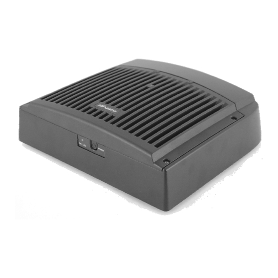
OVERVIEW SCOPE Posiflex TX-3700 series presents a whole new generation POS terminal with the most reliable FanFree system and carries a brilliant performance to user in order to face the busiest situation.TX-3700 Series applies Intel Cedar view-D2550 1.86G, 1M Cache, Dual Core CPU technology;... - Page 7 DDR3 memory expansion up to 4GB max. Integrated upgrade kit: WB-6812 Wall mount bracket. Preload OS Win XP Pro, Win 7, POS Ready 7, POSReady 2009, Linux 24V Power USB cable for compatible printer TX-3700 series Technical Manual Page 5...
-
Page 8: General Specification
XP Pro, POSReady 7(32 bit), Win 7 (32 bit), POSReady COM4 and VGA2 port can not co-exist, and must be specified on order. 2 +5V output configured by software settings; +12V output configured by jumper settings. TX-3700 series Technical Manual 6... -
Page 9: Power Source
VGA and COM2/3 +12V: 1A. VGA power supply through software setting and COM2/3 through jumper setting. SYSTEM POWER ON/OFF CONTROL One main power ON/OFF switch in the front bezel of main unit. Power OFF to ON duration: 10 seconds min. TX-3700 series Technical Manual 7... -
Page 10: Hdd In Hdd Cavity Of Main Unit
Non-operating: 10%RH ~ 80%RH, non-condensing, max. wet bulb 28.9°C (84.0°F) ACCESSORIES User’s manual: 1 copy Power adapter 12 V DC plus a power cord Product Information CD or Recovery CD or DVD of preloaded OS TX-3700 series Technical Manual 8... -
Page 11: Compliance Approvals
1 Gb 2 GB 2 GB 1 Gb 1 GB 2 GB HDD kit or SSD kit (SSD can’t coexist with HDD in main unit) RELIABILITY SPECIFICATION Whole System MTBF: 50,000 Hrs at 90% confidence level. TX-3700 series Technical Manual 9... -
Page 12: System Definitions
(or Pine View D- Manager DC 1.66G Dual Ethernet 10/100/1000 CR Port SATA Port COM3 COM2 COM1 COM4 HDD in SSD in Main Unit Main Unit (+5V/ +12v) (+5V/ +12v) (+5V) RS232 RJ45 RS232 RS232 TX-3700 series Technical Manual 10... -
Page 13: 12 V Dc In Connector
This port is defined as 1G base T or 100 base T or 10 base T LAN port. • This port is utilized by the system in pnp (Plug-N- Play) way, IRQ assigned is not fixed for this port. Most usual observation is IRQ 11. GREEN ORANGE TX-3700 series Technical Manual 11... -
Page 14: Usb0 ~ Usb3
PIN ASSIGNMENT OF EACH 6 PIN RJ11 TYPE MODULAR JACK: PIN # DEFINITION DRAWER KICK 1 PIN 1 DRAWER OPEN SENSE +POWER DRAWER KICK 2 This is a RJ11 jack for cash drawer control providing control ability over max. 2 cash drawers. TX-3700 series Technical Manual 12... -
Page 15: Serial Port Com1
PIN # DEFINITION ALTERNATIVE DEFAULT SETTING BATTWK BATTWK • Please refer to section “UPS DETECTION FUNCTION” in “APPLICATION GUIDE” for BATTWK signal. Please refer to “COM1 APPLICATION COMMENT” in same chapter for remarks on this port. TX-3700 series Technical Manual 13... -
Page 16: Serial Port Com2/4
DEFAULT SETTING PIN 1 • COM3 port appears in form of RJ45 type 10 pin modular connector like the right drawing. However, after use of the conversion cable separately ordered, the pin assignment in DB9 TX-3700 series Technical Manual 14... -
Page 17: Internal Sata Hdd Connector
PIN ASSIGNMENT OF EACH 7 PIN CONTACTS: PIN # DEFINITION HDD POWER CONNECTOR This connector is a small 4 pin connector with housing PIN ASSIGNMENT OF 4 PIN CONTACTS: PIN # DEFINITION + 5 VDC PIN 1 +12 VDC TX-3700 series Technical Manual 15... -
Page 18: Application Guides
+12V DC supplies of COM port can be enabled or disabled. The power supplied from the TX-3700 series to all USB devices on 5 V DC is limited to be within 2.0 Ampere total. The +5V DC in all COM ports is limited to be within 1 Ampere total. -
Page 19: Cash Drawer
Please note that if the system is improperly turned off before a complete boot up procedure, the above preset power on control functions will be disabled until turning off next time after a complete boot up. TX-3700 series Technical Manual 17... -
Page 20: Alarm Clock Wake Up
In this application, there is need for 1 master machine and 1 target machine connected together through LAN. To get LAN chip ID (MAC address) of the target machine, please run the target TX-3700 series Technical Manual 18... -
Page 21: Forced Power Off
LED module could indicate power on status while the system remains off. In such case, please use the forced power off function to cancel the error and wait for 10 seconds before switching on again. TX-3700 series Technical Manual 19... -
Page 22: Vga Port
The external monitor connector is D sub 3 x 5 connector and can be set to support power to specific Posiflex monitor as 2 display. However, the power support in this port should be disabled if the specific Posiflex monitor is no longer used. TX-3700 series Technical Manual 20... -
Page 23: Hardware Details
HARDWARE DETAILS MAIN BOARD COMPONENT SIDE LED1 Touch1 SO-DIMM 1 BAT1 KEYBRD JCOMS1 USB7 CN10 CN11 LAN1 CN12 COMA1 CN14 COM3 CN13 CN15 CN17 CN16 AUDIO1 VGA1 TX-3700 series Technical Manual 21... -
Page 24: Solder Side
SOLDER SIDE TX-3700 series Technical Manual 22... -
Page 25: Jumpers And Connectors
HDR 2x4 (For XP-3000/3300 only) HDR 2x3 COM 2/3 +12V POWER SUPPLY HDR 1x2 SELECT XP-3000/3300 or TX-3700 HDR 1x3 SELECT XP-3000/3300 or TX-3700 JCOMS HDR 1x3 CMOS Setting KEYBRD HDR 1x4 w/H PS2 KB HEADER TX-3700 series Technical Manual 23... -
Page 26: On Solder Side
SELECT LCD POWER OPEN To support EUP But no support LAN/Alram/modem wake up & power fail after power on function SHORT Disable EUP support but Support. LAN/Alram/modem wake up & power fail after power on function TX-3700 series Technical Manual 24... -
Page 27: Touch Panel Of Selection - Jp3
STATUS OF SOLDER SIDE MODEL SELECT 1 - 2 Short XP-4000 2 - 3 Short TX-3700 MODEL SELECT (For TX- 3700 only) – JP5 STATUS OF RAID_RST ON SOLDER SIDE MODEL SELECT SHORT FOR XP OPEN FOR TX TX-3700 series Technical Manual 25... -
Page 28: Cr2 Control - Jp6 & 7
STATUS OF JP12 ON SOLDER STATUS SIDE 1-2 Short FOR 12V CR 2–3 Short FOR 24V CR(XP Model only) JP13 : Model Select STATUS OF JP12 ON SOLDER STATUS SIDE 1-2 Short FOR XP 2–3 Short FOR TX TX-3700 series Technical Manual 26... -
Page 29: Jp14 : Software Awareness Of Ups Status
JP17 : COM PORT DC SUPPLY SELECT STATUS OF JP17 ON SOLDER STATUS SIDE 1-2 Short COM3 Pin1 connected as 12V DC 2–3 Short COM3 Pin1 connected as DCD JP18 : COM PORT DC SUPPLY SELECT TX-3700 series Technical Manual 27... - Page 30 2. When BIOS setup is different with jumper setting of 5 V DC or 12 V DC, the COM port will not have any power supply in this situation. Please make sure the BIOS and Jumper setting before the function needs to be available. TX-3700 series Technical Manual 28...
-
Page 31: Com4 Board For Tx-3700
Connector to main board. HDR 1 x 3 COM4 power supply coltrol. COM4 power supply control – JP1 Status of J3 on Printer control board. Status J3 1-2 Short +5V power supply. J3 1-2 Open TX-3700 series Technical Manual 29... -
Page 32: Service And Spare Parts
This chapter is intended for describing how to disassemble the main unit which the most important part of TX-3700 series. Firstly, please unfasten these four screws as circled in the following picture. After releasing these four screws, the cover can be separated from the main unit as the lower right picture. -
Page 33: Install Optional Ssd Hdd
VGA port. Push the direction as shown in the picture and separate the metal cover from back- cover. TX-3700 series Technical Manual 31... -
Page 34: Install Ddr2 Sodimm And Replace Mainboard
Careless replacement of main board with deviation as minor as upgraded CPU may result in thermal/mechanical/electrical damage. To reassemble the whole system back, please just do the counter actions in reverse order. TX-3700 series Technical Manual 32... -
Page 35: Spare Parts List
“S.” indicates the alternative selections available for that position. Please be noted that the information here is for reference only. It may be revised without notice as time goes on. TX-3700 SERIES SPARE PARTS LIST Pos. Part Number Description... - Page 36 TX-3700 M/B w/CPU Intel Cedar View-D2550 1.86G 35514001000 & BIOS Lable, Ver.A0 21863227512 Flat Cable for XP-PRT, L=130mm 15480108010 Jump Cover 21955016003 2.5” SATA HDD 160G 35465001000 Cable Set for 2.5” SATA HDD & SSD 10556027082 Hexagon Head Screw #4.8*8.2 mm TX-3700 series Technical Manual 34...
- Page 37 Power Cord for India for Power Adaptor NON03 21868900500 80W/120W/150W, L=1800mm, IEC 320-C5 Power Cord for Argentina for Power Adaptor NON04 14500510110 80W/120W/150W, 3 wire, L=1800mm, IEC320-C5 NON05 14510540010 Carton for TX-3000/3700 NON06 14510900010 PE Foam for TX Series TX-3700 series Technical Manual 35...
- Page 38 User Manual for TX-3700 TX-3700 series Technical Manual 36...
-
Page 39: Assembly Drawing
ASSEMBLY DRAWING TX-3700 series Technical Manual 37...
Need help?
Do you have a question about the TX-3700 Series and is the answer not in the manual?
Questions and answers