FUTABA FASSTest-2.4GHz T18SZ Series Instruction Manual
Advanced spread spectrum technology extended system telemetry
Hide thumbs
Also See for FASSTest-2.4GHz T18SZ Series:
- Instruction manual (177 pages) ,
- Software update changes (18 pages) ,
- Manual (12 pages)
Table of Contents
Advertisement
Quick Links
Advertisement
Table of Contents

Related Manuals for FUTABA FASSTest-2.4GHz T18SZ Series


Summary of Contents for FUTABA FASSTest-2.4GHz T18SZ Series
- Page 1 1M23N00000...
-
Page 2: Table Of Contents
TABLE OF CONTENTS When turning on ..........32 INTRODUCTION..........4 When turning off ..........32 ●Support and Service ......... 4 ●Registration of the user's name ..... 32 ●Application, Export, and Modification ... 5 ●Home screen ............ 33 ●Definitions of Symbols ........6 ●Screen lock............ - Page 3 TABLE OF CONTENTS Timer ............... 84 RUD to AIL ........... 130 T1-T6 Setting ..........86 Camber Mix ..........131 Multiprop ............87 ELE to Camber ..........133 Function Name ..........88 Camber FLP to ELE ........134 Telemetry............89 Butterfly ............135 Telemetry:receiver [battery] ......
-
Page 4: Introduction
Email: futabaservice@hobbico.com OUTSIDE NORTH AMERICA Please contact your Futaba importer in your region of the world to assist you with any questions, problems or service needs. Please recognize that all information in this manual, and all support availability, is based upon the systems sold in North America only. -
Page 5: Application, Export, And Modification
Prior approval of the appropriate government authorities may be required. If you have purchased this product from an exporter outside your country, and not the authorized Futaba distributor in your country, please contact the seller immediately to determine if such export regulations have been met. - Page 6 Federal Communications Commission Interference Statement (for U.S.A.) This equipment has been tested and found to comply with the limits for a Class B digital device, pursuant to Part 15 of the FCC Rules. These limits are designed to provide reasonable protection against harmful interference in a residential installation.
- Page 7 EEPROM memory (which does not require periodic replacement) and not a battery, the transmitter still should have regular checkups for wear and tear. We recommend sending your system to the Futaba Service Center annually during your non-flying-season for a complete checkup and service.
- Page 8 Use only the Futaba special charger included with this set or other chargers approved by Futaba to charge the LiFe batteries in the T18SZ transmitter included with this set. It is important to understand the operating characteristics of LiFe/NiMH/NiCd batteries.Always read the specifications printed on the label of your LiFe/NiMH/NiCd battery and charger prior to use.
- Page 9 At the flying field To prevent possible damage to your radio gear, turn the power switches on and off in the proper sequence: 1. Pull throttle stick to idle position, or otherwise disarm your motor/engine. 2. Turn on the transmitter power and allow your transmitter to reach its home screen. 3.
-
Page 10: Before Use
BEFORE USE Features FASSTest system The T18SZ transmitter has adopted the newly developed bidirectional communication system "FASSTest" . Data from the receiver can be checked in your transmitter. FASSTest is a maximum 18channels (linear 16 channels + switch 2 channels) 2.4GHz dedicated system. Color touch screen LCD T18SZ has a HVGA full color Backlight LCD touch screen. -
Page 11: Contents And Technical Specifications
Contents and Technical Specifications (Specifications and ratings are subject to change without notice.) Your T18SZ includes the following components: • T18SZ transmitter for airplanes or helicopters • R7008SB Receiver • FT2F2100BV2 LiFe battery & charger • Switch harness • Neck strap *The set contents depend on the type of set. - Page 12 TRAINER function instructions). The part number of this cord is: FUTM4405. • Servos - there are various kinds of servos. Please choose from the servos of Futaba what suited the model and the purpose of using you. If you utilize a S.BUS system, you should choose a S.BUS servo. An analog servo cannot be used if "FASSTest12CH mode"...
-
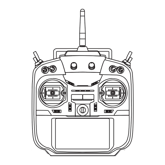
Page 13: Transmitter Controls
Transmitter controls ● Monitor LED ● Antenna ● Carrying handle ● Dial LD.RD ● Switch ● Switch SA.SB.SE.SF SC.SD.SG.SH ● Slide lever ● Slide lever ● Stick ● Stick ● Power Switch ● Digital trim T1 ~ T6 ● Hook ●... - Page 14 Transmitter's Antenna: CAUTION As with all radio frequency transmissions, the strongest area of signal transmission is from the Please do not grasp the transmitter's sides of the transmitter's antenna. As such, the antenna during flight. antenna should not be pointed directly at the model. D o i n g s o m a y d e g r a d e t h e q u a l i t y o f t h e R F If your flying style creates this situation, easily transmission to the model...
- Page 15 How to turn transmitter power ON/OFF When turning on the power, the T18SZ transmitter will begin emmiting RF automatically after it confirms the surrounding RF conditions. The status of the transmitter is displayed by LED at the upper part of the front of a T18SZ. *If THR stick is high, the next WARNING screen will come out.
- Page 16 Stick control : Airplane Example A general model example. (There is also a different operational model.) Roll axis Control Pitch axis Control Right roll Nose Up The right aileron is to the up. Elevator stick The left aileron Aileron stick is in the down.
- Page 17 Stick control : Helicopter Example A general model example. (There is also a different operational model.) Roll axis Control Pitch axis Control Right roll Nose Up Elevator stick Aileron stick To the right (moved to the bottom) Level flight Level flight Neutral Neutral Left roll...
- Page 18 Stick control : Multicopter Example A general model example. (There is also a different operational model.) Roll axis Control Pitch axis Control Right roll Nose Up Right slide Elevator stick Aileron stick Back slide To the right (moved to the bottom) Hovering Level flight Hovering...
-
Page 19: Switch (Sa-Sh)
Switch (SA-SH) SF : SH : 2 positions; Alternate; 2 positions; Momentary; Long lever Long lever SE : SG : 3 positions; Alternate; 3 positions; Alternate; Short lever Short lever SA : SD : 3 positions; Alternate; 3 positions; Alternate; Short lever Short lever SB :... - Page 20 Digital Trims T1-T6 This transmitter is equipped with 6 digital trims. Each time you press a trim button, the trim position moves one step. If you continue pressing it, the trim position starts to move faster. In addition, when the trim position returns to the center, the tone will change.
- Page 21 Slide Lever LS (right), RS (Left): The Linear Slider LS and RS offer analog input. *The T18SZ transmitter beeps when the lever comes to the center. *You can select a slide lever and set the movement direction on the setting screen of mixing functions. <Before Use>...
- Page 22 Touch Panel Stylus pen Touch the panel with your finger or the attached stylus pen, which is also used as a toolbox, to enter ●You may use this tool data. as a stylus pen. *Plastic film is attached to the touch panel. Please be careful so that you don't scratch the touch panel with anything hard such as a metal object.
-
Page 23: Stick Adjustment
Stick Adjustment Adjustment of the stick lever length You can adjust the length of stick levers, as you like. It is recommended to adjust the length of the sticks in line with your hand size. Lever Head Lever Head Side cover 1. - Page 24 Stick Adjustment Adjustment of the stick lever angle •Stick Tension (J4) You can make fine adjustments to the angle of (Mode 1/2) •Stick Tension (J2) a stick lever either inwards or outwards from the (Mode 2) center stick position. 1.5mm hexagonal wrench •Stick Tension (J3) (Mode 1) •Stick Tension (J1)
-
Page 25: Sd Card
SD cards with a memory size between 32MB and 2GB. SD card reader/writer Saving model data and update files (released from Futaba) into the SD card, you can use those files on your T18SZ transmitter. Equipment for SD card slot reading and writing SD cards is available at most electronics stores. -
Page 26: Connector/Plug
Connector/Plug S.BUS connector (S.I/F) When setting an S.BUS servo and telemetry sensor, connect them both here. (Supply power by 3-way hub or 2-way cord.) Earphone Earphone plug Plug Connecting a stereo headphone to this plug, the speech information of telemetry can be heard. Charge Plug Connector for battery charger... - Page 27 Transmitter LiFe Battery FT2F2100B V2 This 2P connector to be FT2F2100B V2 Inserting/removing the FT2F2100B V2 connected to a transmitter. LiFe Battery The balance charge connector is not connected in the state where the battery is set to a transmitter. ①...
- Page 28 * If there is any problem, the message "Backup Error" will be shown the next time when you turn on the power of the transmitter. Do not use the transmitter as it is. Send it to the Futaba service center. Red sold WARNING...
-
Page 29: Receiver Nomenclature
Receiver nomenclature Danger Before using the receiver, be sure to read the precautions listed in the following pages. Don't connect a connector, as shown in a before figure. Receiver R7008SB *It will short-circuit, if it connected in this way. A short circuit across the battery terminals may cause abnormal heating, fire and burns. - Page 30 Danger Don't touch wiring. * There is a danger of receiving an electric shock. Do not short-circuit the battery terminals. * A short circuit across the battery terminals may cause abnormal heating, fire and burns. Please double check your polarity ( + and -...
-
Page 31: Receiver's Antenna Installation
Receiver's Antenna Installation The R7008SB has two antennas. In order to maximize signal reception and promote safe modeling Futaba has adopted a diversity antenna system. This allows the receiver to obtain RF signals on both antennas and fly problem-free. *Must be kept as straight as possible. - Page 32 Safety precautions when Mounting the Servo you install receiver and *If the servo case contacts the airframe directly, vibration servos. will travel to and possibly damage the servo. WARNING Wood screw 2.3-2.6mm nut washer Rubber Rubber Connecting connectors grommet grommet Brass eyelet Brass eyelet Servo mount...
-
Page 33: S.bus/S.bus2 Installation
S.BUS/S.BUS2 Installation This set uses the S.BUS/S.BUS2 system. The wiring is as simplified and clean mounting as possible, even with models that use a large number of servos. In addition, the wings can be quickly installed to the fuselage without any erroneous wiring by the use of only one simple wire, even when there are a large number of servos used. -
Page 34: S.bus Wiring Example
S.BUS Wiring example *When using 8/SB as S.BUS, you must set the receiver to Receiver Mode B or Mode D. See R7008SB CH MODE TABLE. ●S.BUS Servo Since the channel number is memorized by the S.BUS itself, any connector can be used. When the SBD-1 (sold separately) is used, ordinary servos can be used with the S.BUS Battery... -
Page 35: S.bus2 System
S.BUS2 System When using the S.BUS2 port, an impressive array of telemetry sensors may be utilized. S.BUS2 TABLE S.BUS2 S.BUS Servo Servo Receiver port Telemetry sensor S.BUS2 S.BUS Gyro Gyro S.BUS ○ ○ × S.BUS2 × (※) ○ ○ (※) Don't connect S.BUS Servo, S.BUS Gyro to S.BUS2 connector. -
Page 36: S.bus/S.bus2 Devicesetting
S.BUS/S.BUS2 device setting S.BUS/S.BUS2 servos or a telemetry sensor can be connected directly to the T18SZ. Channel setting and other data can be entered for the S.BUS/S.BUS2 servos or sensors. T18SZ 1. Connect the S.BUS device you want to set with as shown in the figure. -
Page 37: Telemetry System
Telemetry System The R7008SB receiver features bi-directional communication with a FASSTest Futaba transmitter using the S.BUS2 port. Using the S.BUS2 port an impressive array of telemetry sensors may be utilized. It also includes both standard PWM output ports and S.BUS output ports. -
Page 38: Basic Operation
BASIC OPERATION Home screen Use the touch sensor to select the following display area to call each setting screen, and push the EDIT button. The setting screen appears. Airplane/Glider Home Screen Model Name Timer display screen • The model name that •... - Page 39 Helicopter Home Screen Throttle/Pitch Position Display • Throttle and pitch position is displayed here. Push the EDIT button to call the throttle curve or pitch curve setting screen directly. *Condition hold operation is displayed. ("IS ON") To activate/deactivate Condition Hold: 1.Move the cursor to [CND HOLD].
-
Page 40: Screen Lock
Screen lock To prevent the data from being changed by erroneous touching of the touch sensor during flight, a function which makes an touch sensor impossible temporarily. How to lock 1. The home screen is displayed. 2. Press the S1 button for about 1 second. "LOCK"... -
Page 41: Link Procedure
Link procedure (T18SZ/R7008SB) Each transmitter has an individually assigned, unique ID code. In order to start operation, the receiver must be linked with the ID code of the transmitter with which it is being paired. Once the link is made, the ID code is stored in the receiver and no further linking is necessary unless the receiver is to be used with another transmitter. - Page 42 10. When a telemetry function is enabled, the receiving interval (down-link interval) of sensor data can be changed. If a DL interval is increased, the response of the sensor data display becomes slower, but stick response will improve. Initial value: 1.0s Adjustment range: 0.1s~2.0s * If there are many FASSTest systems turned on around your receiver, it might not link to your transmitter.
-
Page 43: Range Testing Your R/C System
Range Testing Your R/C System It is extremely important to range check your models prior to each flying session. This enables you to ensure that everything is functioning as it should and to obtain maximum enjoyment from your time flying. The T18SZ transmitter incorporates a system that reduces its power output and allows you to perform such a range check. -
Page 44: Functions Of System Menu
SYSTEM MENU The System Menu sets up functions of the transmitter: This does not set up any model data. ● Select [SYSTEM] at the home screen and call the system menu shown below by touching the RTN button. ● Scrolling the touch sensor to select the function you want to set and call the setup screen by touching the RTN button. -
Page 45: Display
DISPLAY LCD contrast adjustment and automatic key lock The following LCD screen adjustments and auto ● Backlighting brightness adjustment power off setting are possible: ● Backlighting off timer adjustment ● Automatic key lock setup ● Select [DISPLAY] at the system menu and call the setup screen shown below by touching the RTN button. -
Page 46: System Timer
SYSTEM TIMER Resets the accumulated timer. This function resets the system timer displayed MODEL timer: Displays the total accumulated time on each model from the last time the on the home screen. timer was reset. ● T18SZ has two type system timers. ●... -
Page 47: User Name
USER NAME User name registration This function registers the T18SZ user name. *A name of up to 12 characters can be entered as the user name. (Space is also counted as 1 character.) ● Select [USER NAME] at the system menu and call the setup screen shown below by touching the RTN button. -
Page 48: Function
SOUND Turns off the buzzer. 3 independent sound volumes: "WARNING", "VOICE" and others, are available. "LOW BATTERY" adjusts low battery alarm voltage to match a battery. ● Select [SOUND] at the system menu and access the setup screen shown below by touching the RTN button.
Need help?
Do you have a question about the FASSTest-2.4GHz T18SZ Series and is the answer not in the manual?
Questions and answers