Table of Contents
Advertisement
Quick Links
Advertisement
Table of Contents

Related Manuals for Global American 3301040


Summary of Contents for Global American 3301040
- Page 1 User’s Manual 3301040...
-
Page 2: Replacing The Lithium Battery
The lithium battery must be replaced with an identical battery or a battery type recom- mended by the manufacturer (BR2335). Do not throw lithium batteries into the trashcan. It must be disposed of in accordance with local regulations concerning special waste. 3301040 User's Manual... -
Page 3: Table Of Contents
Wake On LAN ................11 LPT1 ..................... 21 Serial Port Selection (RS232C/422/485) ........12 Keyboard & PS/2 Mouse ............22 COM1~COM4 Power Source Special Support ......12 4P Power Connector ..............22 LVDS Voltage Selection .............. 14 IrDA Connector ................22 3301040 User's Manual... - Page 4 Frequency/Voltage Control ................40 PC Health Status .................... 41 IRQs Activity Monitoring .................. 41 IRQ Resources ....................42 Wake Up Events ..................... 42 Howto : Flash the BIOS .............. 43 What if things go wrong ................... 43 Warranty ..................44 3301040 User's Manual...
-
Page 5: Specifications
• Parallel: Supports SPP, EPP and ECP mode • USB: 4 USB ver1.1 ports Environmental and Power • Power Requirements (typical) : 5.79 walt (3301040 VL3/N, Celeron 400 with 128MB RAM) • Chipset: Triple Intel 82551 or Realtek 8100BL for 10/100Mbps or Intel 82540 for •... -
Page 6: Packing List
Before you begin installing your single board computer, please make sure that the following materials have been shipped: > 1 x 3301040 5.25" Embedded Celeron 400 (Celeron 650, PIII 800, PIII 933) SBC > 1 x Quick Installation Guide > 1 x CD-ROM ( for driver used) - Page 7 LV PIII 933MHz with 133MHz FSB and 512K L2 Cache • Ethernet options Intel 82551 10/100 Mbps Intel 82540 10/100/1000 Mbps Realtek 8100BL 10/100 Mbps • Connector options I/O connector type: 3301040-C (standard) Box header type: 3301040-B (optional) 3301040 User's Manual...
-
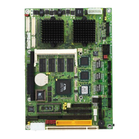
Page 8: Board Image (Boxheader Version)
JFRT1 JVLCD1 RES2 LCD1 LVDS1 VGA1 VGA1 INV1 COM1 AUDIO1 LCD2 CPUF1 SODIM1 CDIN1 LAN3 PC104 LAN2 LAN1 JCF1 USB2 USB1 EATX1 LPT1 DOC1 SIR1 FDD1 COM2-4 KBM1 DIO1 WOL1 IDE2 KBM1 LED1 IDE1 PCI1 LLED1 PWR2 3301040 User's Manual... -
Page 9: Board Layout (Back)
Board Layout (Back) Board Dimension MPCI1 CFD1 Unit: 3301040 User's Manual... -
Page 10: Connector Quick Reference
Serial Port: COM2~COM4 TV-OUT Connector PC104 PC104 for ISA Interface Connector PCI1 PCI Slot / Expansion PCI Slot CPUF1 CPU Fan1 connector DIO1 Digital I/O Connector FDD1 Floppy Disk Drive Connector IDE1 Primary IDE Connector (ATA 33/66) 3301040 User's Manual... -
Page 11: Cmos Jumper Settings
JFRT1 Type : JBAT1: onboard 3-pin header JVLCD1 RES2 LCD1 If the 3301040 refuses to boot due to inappropriate CMOS settings here is how to proceed to clear (reset) the CMOS to its default values. LVDS1 VGA1 CMOS Setup (JBAT1) -
Page 12: Serial Port Selection (Rs232C/422/485)
The voltage of COM 1 could be selected by JV1 & JV2. KBM1 LED1 IDE1 COM1 Power Source Standard PCI1 LLED1 PWR2 POS:12V on pin 9 POS:5V on pin 1 POS:5V on pin 1 and 12V on pin 9 2-3 default setting Standard 3301040 User's Manual... - Page 13 KBM1 COM1 Power Source LED1 IDE1 Standard POS:12V on pin 9 PCI1 LLED1 PWR2 POS:5V on pin 1 POS:5V on pin 1 and 12V on pin 9 2-3 default setting Standard JV6 JV5 JV8 JV7 JV4 JV3 3301040 User's Manual...
-
Page 14: Lvds Voltage Selection
SPEAKER RIGHT JCF1 USB2 CDIN Connector USB1 EATX1 LPT1 DOC1 Connector : CDIN1 SIR1 FDD1 COM2-4 Type : onboard 4-pin header KBM1 DIO1 WOL1 IDE2 KBM1 LED1 IDE1 Description Description PCI1 LLED1 PWR2 CD Left CD Right 3301040 User's Manual... -
Page 15: Vga Connector
Connector : JCF1 DIO1 WOL1 IDE2 KBM1 Type : onboard 3-pin header LED1 IDE1 The CFD could be selected by JCF1 in master or slave. PCI1 LLED1 PWR2 Mode JCF1 Master 1-2 (ON) Slave 2-3 (OFF) default setting Master 3301040 User's Manual... -
Page 16: Cpu Fan Connector
TV-out Connector LAN1 Connector : TV1 Connector JCF1 USB2 USB1 Type: Onboard 6-pin wafer EATX1 LPT1 DOC1 Description SIR1 FDD1 COM2-4 KBM1 Composite Video DIO1 WOL1 IDE2 KBM1 LED1 IDE1 S-Video Y PCI1 LLED1 PWR2 S-Video C 3301040 User's Manual... -
Page 17: 18Bit/24Bit Ttl Flat Panel Connector
FPSCLK USB1 EATX1 LPT1 DOC1 SIR1 FPVDDEN VBIASEN FDD1 COM2-4 KBM1 INV Connector DIO1 WOL1 IDE2 KBM1 Connector : INV1 LED1 IDE1 Type : Onboard 5-pin wafer PCI1 LLED1 PWR2 Description Description +12 V on/off brightness control 3301040 User's Manual... -
Page 18: 36Bit Panel Connector
Signal LAN1 TX1CLK+ TX2CLK+ TX1CLK- TX2CLK- JCF1 USB2 USB1 EATX1 TX1D0+ TX2D0+ LPT1 DOC1 SIR1 TX1D0- TX2D0- FDD1 COM2-4 KBM1 DIO1 WOL1 IDE2 TX1D1+ TX2D1+ KBM1 LED1 TX1D1- TX2D1- IDE1 PCI1 LLED1 PWR2 TX1D2+ TX2D2+ TX1D2- TX2D2- 3301040 User's Manual... -
Page 19: Usb1 Connector (Box Header Version Only)
JCF1 USB2 9 10 USB1 Type:onboard 10-pin box header USB1 EATX1 USB2 LPT1 DOC1 Description Description SIR1 FDD1 COM2-4 KBM1 DIO1 WOL1 USBD0- USBD1- IDE2 KBM1 USBD0+ 6 USBD1+ LED1 9 10 IDE1 USB2 PCI1 LLED1 PWR2 3301040 User's Manual... -
Page 20: Interface Connectors Fdd
PC104 #STEP LAN2 #WRITE DATA #WRITE GATE LAN1 #TRACK 0 #WRITE PROTECT JCF1 USB2 #READ DATA USB1 #HEAD SELECT EATX1 #DISK CHANGE LPT1 DOC1 SIR1 FDD1 COM2-4 KBM1 DIO1 WOL1 IDE2 KBM1 LED1 IDE1 PCI1 LLED1 PWR2 3301040 User's Manual... -
Page 21: Fast Ethernet Connectors
#ERROR JCF1 USB2 USB1 DATA1 #INITIALIZE EATX1 DATA2 #SELECT INPUT LPT1 DOC1 SIR1 DATA3 FDD1 COM2-4 KBM1 DATA4 DIO1 WOL1 IDE2 DATA5 KBM1 LED1 IDE1 DATA6 DATA7 PCI1 LLED1 PWR2 #ACKNOWLEDGE BUSY PAPER EMPTY SELECT LPT 1 3301040 User's Manual... -
Page 22: Keyboard & Ps/2 Mouse
Connector : PWR1 & PWR2 EATX1 LPT1 Type : onboard 4-pin Wafer connector DOC1 SIR1 FDD1 Description COM2-4 KBM1 DIO1 WOL1 IDE2 KBM1 LED1 IDE1 G ND +5 V G ND +12 V PCI1 LLED1 PWR2 +12V PWR2 KBM1 3301040 User's Manual... -
Page 23: Switches And Indicators
CDIN1 LAN3 PC104 LAN2 Connector : HLED (Hard Disk LED) LAN1 JCF1 USB2 Description USB1 EATX1 Hard Disk LED+ LPT1 DOC1 SIR1 FDD1 COM2-4 Hard Disk LED- KBM1 DIO1 WOL1 IDE2 KBM1 LED1 IDE1 PCI1 LLED1 PWR2 3301040 User's Manual... -
Page 24: Led Indicator
LPT1 DOC1 CLOSE (ON) Default SIR1 FDD1 OPEN (OFF) COM2-4 KBM1 DIO1 WOL1 IDE2 KBM1 Reset Connector LED1 IDE1 Connector : RES2 PCI1 LLED1 PWR2 Type : RES2: reset switch connector for reboot Description Description JPWR1 Reset 3301040 User's Manual... -
Page 25: Com2/Com3/Com4 Connector
16 Bit General purpose I/O LAN1 Connector : DIO1 JCF1 USB2 Type : Onboard 20-pin header USB1 EATX1 LPT1 Description Description DOC1 SIR1 FDD1 COM2-4 KBM1 DIO1 WOL1 IDE2 KBM1 LED1 IDE1 PCI1 LLED1 PWR2 COM4 COM3 COM2 +12V 3301040 User's Manual... -
Page 26: System Resources
VIA Tech 3038 PCI to USB Universal Host Controller PS/2 Compatible Mouse Port Numeric data processor Primary IDE controller (dual fifo) VIA Bus Master PCI IDE Controller Secondary IDE controller (dual fifo) VIA Bus Master PCI IDE Controller 3301040 User's Manual... - Page 27 03F6- 03F6 VIA Bus Master PCI IDE Controller 03F6- 03F6 Primary IDE controller (dual fifo) 03F7- 03F7 Standard Floppy Disk Controller 03F8- 03FF Communications Port (COM1) 04D0- 04D1 PCI bus 0CF8- 0CFF PCI bus 4000- 407F PCI bus 3301040 User's Manual...
-
Page 28: Award Bios Setup
BIOS to maximize performance, the factory has the right to choices. Use the arrow keys to select among the items and change these defaults to meet their needs. press <Enter> to accept and enter the sub-menu. 3301040 User's Manual... -
Page 29: Standard Cmos Setup
IDE Primary & Secondary Master/Slave Selecting "Manual" lets you set the remaining fields on this screen. Select the type of fixed disk. "User Type" will let select the number of cylinder, head, etc. Note: PRECOMP=65535 means NONE! [NONE] 3301040 User's Manual... -
Page 30: Ide Hdd Auto Detection
All, But Disk/Key POST does not stop for a keyboard or disk error, but stops for all other errors. Panel Type Select the type of panel. Boot Device Select Select the booting device. 3301040 User's Manual... -
Page 31: Advanced Bios Features
PCs have additional (external) cache memory. When the CPU requests data, the system transfers the request ed data from the main DRAM into cache memory, for even faster access by the CPU. 3301040 User's Manual... - Page 32 Third Boot Device ---> Select Your boot Device Priority. Boot Other Device ---> Select Your boot Device Priority. Swap Floopy Drive ---> If the system has two floopy drives, choose enable to assign physical drive B to logical drive A and vice-versa. 3301040 User's Manual...
-
Page 33: Integrated Peripherals
OnChip Primary / Secondary PCI IDE The integrated peripheral controller contains an IDE interface with Select Enabled if your system has a floppy disk controller (FDC) in- support for two IDE channels. Select Enabled to activate each channel separately. 3301040 User's Manual... -
Page 34: Power Management Setup
If Advanced Power Management (APM) is installed on your system, electing Yes gives better power savings. Video Off Option Controls what causes the display to be switched off Suspend -> Off Always On All Mode -> Off 3301040 User's Manual... - Page 35 Select the state after power failure. Wake Up Events Setting an event on each device listed to awaken the system from a soft off state. LPT & COM HDD & FDD PCI Master Power On by PCI Card 3301040 User's Manual...
-
Page 36: Pnp/Pci Configuration
The Award Play and Play BIOS can automatically configure all the boot and Plug-and-Play compatible devices. If you select Auto, all the inter- rupt request (IRQ) and DMA assignment fields disappear, as the BIOS automatically assigns them. 3301040 User's Manual... -
Page 37: Advanced Chipset Features
SDRAM cannot handle the lower cycle length and may become unstable. memory from 15MB and up unavailable to the system. Expansion cards So, set the SDRAM Cycle Length to 2 for optimal performance if possible but increase it to 3 if your system becomes unstable. 3301040 User's Manual... - Page 38 This function determines whether there's a delay before any writes to the PCI bus. If this is enabled, then writes to the PCI bus are executed immediately (with zero wait states), as soon as the PCI bus is ready to 3301040 User's Manual...
- Page 39 AGP read performance, enable this option but disable it if you experience weird graphical anomalies like wireframe effects and pixel PCI # 2 Access # 1 Retry artifacts after enabling this option. This BIOS feature is linked to the CPU to PCI Write Buffer. Normally, the 3301040 User's Manual...
-
Page 40: Dma Resources
DMA Resources Frequency/Voltage Control DMA Resources 0-7 Assignment Auto Detect DIMM/PCI Clk [Enabled] [Disabled] Spread Spectrum [Disabled] [0.25 %] [0.50 %] 3301040 User's Manual... -
Page 41: Pc Health Status
IRQ13 (Coprocessor) input lines, if your computer contains a monitoring system. IRQ14 (Hard Disk) 12V ---> These fields display the current voltage of up to seven voltage input lines, if your computer contains a monitoring system. IRQ15 (Reserved) 3301040 User's Manual... -
Page 42: Irq Resources
RTC (real-time clock) alarm awakens the system from IRQ-12 assigned to Suspend mode. Primary INTR ---> When Enabled, an event occurring on each listed IRQ-14 assigned to device restarts the global timer for Standby mode. IRQs Activity Monitoring IRQ-15 assigned to 3301040 User's Manual... -
Page 43: Howto : Flash The Bios
2. Boot the system to DOS (with floppy or HD) Cacheable,hit Esc, F10, Save and reboot. 3. Be sure that the System BIOS cacheable option in your BIOS is enabled! If so replace (while the computer is powered on) the BIOS chip 3301040 User's Manual... -
Page 44: Warranty
Return authorization must be obtained from the vendor before returned merchandise will be accepted. Authorization can be obtained by calling or faxing the vendor and requesting a Return Merchandise Authorization (RMA) number. Returned goods should always be accompanied by a clear problem description. 3301040 User's Manual... - Page 45 Any advice or comments about our products and service, or anything we can help you with please don’t hesitate to contact with us. We will do our best to support you for your products, projects and business. Global American Inc. Address...
Need help?
Do you have a question about the 3301040 and is the answer not in the manual?
Questions and answers