
Related Manuals for Global American 3308490


Summary of Contents for Global American 3308490
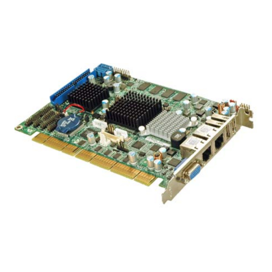
- Page 1 3308490 User’s Manual Half-Size PCISA SBC with Intel Atom N270 Processor Version 1.0...
- Page 2 Copyrights This document is copyrighted and all rights are reserved. It does not allow any non authorization in copied, photocopied, translated or reproduced to any electronic or machine readable form in whole or in part without prior written consent from the manufacturer.
- Page 3 Packing List The items listed below should all be included in the 3308490 package. 1 x 3308490 PCISA Motherboard 1 x LPT and RS-232 cable 2 x SATA cable 1 x USB cable 1 x Mini jumper pack 1 x Utility CD 1 x Manual Images of the above items are shown in Chapter 3.
-
Page 4: Table Of Contents
Table of Contents 1 INTRODUCTION......................1 1.1 I ......................2 NTRODUCTION 1.2 O ...................... 3 VERVIEW HOTO 1.3 P ..............4 ERIPHERAL ONNECTORS AND UMPERS 1.4 T ..................5 ECHNICAL PECIFICATIONS 2 DETAILED SPECIFICATIONS .................. 8 2.1 D ......................9 IMENSIONS 2.1.1 Board Dimensions.................... - Page 5 2.5.6.1 LPC Interface .................... 20 2.5.6.2 16C550 UARTs ..................20 2.5.6.3 Digital Input/Output.................. 21 2.5.6.4 Enhanced Hardware Monitor..............21 2.5.6.5 Fan Speed Controller ................21 2.5.6.6 Keyboard/Mouse Controller ..............21 2.5.6.7 Parallel Port....................21 2.5.7 PCI Bus ......................21 2.5.7.1 PCI Edge Connector ................. 22 2.5.7.2 ISA Edge Connector .................
- Page 6 4.2.3 Backlight Inverter Connector ................37 4.2.4 Battery Connector.................... 38 4.2.5 BIOS Programming Connector................ 38 4.2.6 CompactFlash® Socket..................39 4.2.7 Digital I/O Connector ..................41 4.2.8 Fan Connector ....................42 4.2.9 Floppy Disk Connector ..................43 4.2.10 Front Panel Connector .................. 44 4.2.11 IDE Connector ....................
- Page 7 5.6.3 CF Card Setup ....................71 5.6.4 COM2 RS-232/422/485 Selection Jumper ............71 5.6.5 LCD Panel Type Selection ................72 5.6.6 LVDS Voltage Selection..................72 5.7 C ................... 73 HASSIS NSTALLATION 5.7.1 Airflow......................73 5.7.2 Motherboard Installation................. 74 5.8 I ............
- Page 8 Figure 1-1: 3308490 .......................2 Figure 1-2: 3308490 Overview (Front)..................3 Figure 1-3: 3308490 Overview (Rear)...................4 Figure 2-1: 3308490 Dimensions (mm) ................9 Figure 2-2: External Interface Panel Dimensions (mm) ............10 Figure 2-3: Data Flow Block Diagram ..................11 Figure 2-4: CPU and Northbridge Connections.................12 Figure 2-5: Intel®...
- Page 9 Figure 4-22: TV Connector Pinout Locations ................56 Figure 4-23: USB Connector Pinout Locations .................57 Figure 4-24: 3308490 External Peripheral Interface Connector ........58 Figure 4-25: LAN Connector......................58 Figure 4-26: VGA Connector .......................60 Figure 5-1: CF Card Installation ....................66 Figure 5-2: ATX Power Control Connector ................67 Figure 5-3: Jumper Location .......................69...
- Page 10 Figure 7-15: VGA Driver Installation Finish Screen ............... 152 Figure 7-16: LAN Driver Welcome Screen ................153 Figure 7-17: LAN Driver Welcome Screen ................153 Figure 7-18: LAN Driver Installation ..................154 Figure 7-19: LAN Driver Installation Complete............... 154 Figure 7-20: AC'97 Audio ......................155 Figure 7-21: AC’97 Audio Driver Options................
- Page 11 List of Tables Table 1-1: Technical Specifications....................7 Table 2-1: Supported HDD Specifications..................18 Table 2-2: Power Consumption....................25 Table 3-1: Packing List.........................29 Table 3-2: Power Consumption....................30 Table 4-1: Peripheral Interface Connectors ................34 Table 4-2: Rear Panel Connectors ....................34 Table 4-3: ATX Power Supply Enable Connector Pinouts ............36 Table 4-4: Audio Connector Pinouts (9-pin) ................37 Table 4-5: LCD Backlight Connector Pinouts................37 Table 4-6: Battery Connector Pinouts ..................38...
- Page 12 Table 4-26: USB Port Pinouts...................... 5 9 Table 4-27: VGA Connector Pinouts................... 6 0 Table 5-1: Jumpers ........................6 8 Table 5-2: AT/ATX Power Selection Jumper Settings...............70 Table 5-3: Clear CMOS Jumper Settings..................70 Table 5-4: CF Card Setup Jumper Settings ................7 1 Table 5-5: COM2 RS-232/422/485 Selection Jumper Pinouts...........71 Table 5-6: LCD Panel Type Selection Jumper Settings ............72 Table 5-7: LVDS Voltage Selection Jumper Settings..............73...
-
Page 14: Introduction
Chapter Introduction Page 1... -
Page 15: Introduction
Finally, an SDVO connector provides a direct connection from the Northbridge SDVO port to an GAI SDVO graphics card. 512 MB of DDR2 memory is included with the 3308490 (a custom option with a DDR2 SO-DIMM slot is available). Permanent storage is provided through dual SATA ports, offering 300 MB/s transfer speeds, RAID 0 and RAID 1 support. -
Page 16: Overview Photo
1.2 Overview Photo The 3308490 has a wide variety of peripheral interface connectors. F igure 1-2 is a labeled photo of the peripheral interface connectors on the 3308490. Figure 1-2: 3308490 Overview (Front) Page 3... -
Page 17: Peripheral Connectors And Jumpers
Figure 1-3: 3308490 Overview (Rear) 1.3 Peripheral Connectors and Jumpers The 3308490 has the following connectors on-board: 1 x ATX power control connector 1 x Audio kit connector 1 x Backlight inverter connector 1 x Battery connector 1 x BIOS programming header 1 x CompactFlash®... -
Page 18: Technical Specifications
2 x SATA connectors 1 x SDVO connector 1 x TV connector 2 x USB connectors The 3308490 has the following external peripheral interface connectors on the board rear panel. 2 x Network ports 2 x USB ports 1 x VGA port... - Page 19 Specification 3308490 512 MB of DDR2 RAM integrated (a DDR2 SO-DIMM slot is a Memory custom option) One CompactFlash® socket CompactFlash® Super I/O iTE IT8718F LVDS Display HDTV SDVO BIOS AMI BIOS label Through HD Audio or AC’97 audio kit...
-
Page 20: Table 1-1: Technical Specifications
Specification 3308490 Dimensions (LxH) 185 mm x 127.6 mm Weight (GW/NW) 1000 g / 252 g Table 1-1: Technical Specifications Page 7... -
Page 21: Detailed Specifications
Chapter Detailed Specifications Page 8... -
Page 22: Dimensions
2.1 Dimensions 2.1.1 Board Dimensions The dimensions of the board are listed below: Length: 185 mm Height: 127.6 mm Figure 2-1: 3308490 Dimensions (mm) Page 9... -
Page 23: External Interface Panel Dimensions
2.1.2 External Interface Panel Dimensions External peripheral interface connector panel dimensions are shown in F igure 2-2. Figure 2-2: External Interface Panel Dimensions (mm) Page 10... -
Page 24: Data Flow
2.2 Data Flow Figure 2-3 shows the data flow between the two on-board chipsets and other components installed on the motherboard and described in the following sections of this chapter. Figure 2-3: Data Flow Block Diagram Page 11... -
Page 25: Intel ® Atom ™ Processor
2.3 Intel® Atom™ Processor 2.3.1 Overview The 3308490 comes with an embedded 45 nm 1.60 GHz Intel® Atom™ N270 processor. The processor supports a 533 MHz FSB and has a 512 KB L2 cache. The low power processor has a maximum power of 2.5 W. The CPU is shown in Figure 2-4 below. -
Page 26: Front Side Bus (Fsb)
533 MHz FSB. The Northbridge connections are shown in Figure 2-4 and described below. 2.4.1 DDR2 Controller There is 512 MB of memory on the 3308490. The memory has the following specifications: 512 MB embedded (up to 2.0 GB can be installed on customized board with... -
Page 27: Graphics
Support for DDR2 at 400 MHz and 533 MHz No support for Dual-Channel Interleaved mode of operation Enhanced Addressing support (Swap only) The embedded memory is shown in Figure 2-4 above. 2.4.2 Graphics The Intel® 945GSE Northbridge chipset has an Intel® Gen. 3.5 integrated graphics engine that supports the following display devices: Analog CRT LVDS... -
Page 28: Sdvo And Dvi
1080i 1080p 2.4.2.4 SDVO and DVI The SDVO port on the solder side of the 3308490 connects directly to the SDVO output on the Intel® 945GSE. The SDVO connector is connected to an GAI SDVO graphics card. Concurrent operation of PCIe x 1 with SDVO... -
Page 29: Figure 2-5: Intel® Ich7M Southbridge Connections
33 MHz PCI operations Supports ACPI Power Management Logic Contains: Enhanced DMA controller Interrupt controller Timer functions Integrated SATA host controller with DMA operations interfaced to two SATA connectors on the 3308490 Integrated IDE controller supports Ultra ATA 100/66/33 Page 16... -
Page 30: Hd Audio Controller
Supports the four USB 2.0 devices on the 3308490 with four UHCI controllers and one EHCI controller Complies with System Management Bus (SMBus) Specification, Version 2.0 Supports Audio Codec ’97 (AC’97) Revision 2.3 Supports Intel® High Definition Audio Contains Low Pin Count (LPC) interface... -
Page 31: Ide Connector
Controller Interface Table 2-1: Supported HDD Specifications 2.5.2.2 CompactFlash® Slot The CompactFlash® slot on the 3308490 is interfaced through the IDE interface on the Intel® ICH7M Southbridge. The CompactFlash® slot is on the solder side of the 3308490. 2.5.3 Real Time Clock 256 bytes of battery backed RAM is provided by the Motorola MC146818 A real time clock (RTC) integrated into the ICH7M. -
Page 32: Sata Controller
Up to six high-speed, full-speed or low-speed USB devices are supported by the Intel® ICH7M on the 3308490. High-speed USB 2.0, with data transfers of up to 480 MB/s, is enabled with the Intel® ICH7M integrated Enhanced Host Controller Interface (EHCI) compliant host controller. -
Page 33: Lpc Interface
Figure 2-6: Super I/O Connections Some of the features of the iTE IT8718F chipset are listed below: ACPI and LANDesk Compliant Enhanced Hardware Monitor Fan Speed Controller Two 16C550 UARTs for serial port control One IEEE 1284 Parallel Port Keyboard Controller Watchdog Timer Some of the Super I/O features are described in more detail below: 2.5.6.1 LPC Interface... -
Page 34: Digital Input/Output
2.5.6.3 Digital Input/Output The input mode supports switch debouncing or programmable external IRQ routing. The output mode supports two sets of programmable LED blinking periods. 2.5.6.4 Enhanced Hardware Monitor The Super I/O Enhanced Hardware Monitor monitors three thermal inputs, VBAT internally, and eight voltage monitor inputs. -
Page 35: Pci Edge Connector
Integrated PCI arbiter supports up to seven PCI bus masters 2.5.7.1 PCI Edge Connector The PCI interface is connected directly to the PCI portion of the edge connector on the 3308490. 2.5.7.2 ISA Edge Connector The PCI interface is connected to the ISA edge connector through the iTE IT8888G PCI-to-ISA chip. -
Page 36: Spi Bus Components
Integrated 10/100/1000 transceiver Auto-Negotiation with Next Page capability Supports PCI Express™ 1.1 Supports pair swap/polarity/skew correction Crossover Detection & & Auto-Correction Wake-on-LAN and remote wake-up support Microsoft® NDIS5, NDIS6 Checksum Offload (IPv4, IPv6, TCP, UDP) and Segmentation Task-offload (Large send and Giant send) support Supports Full Duplex flow control (IEEE 802.3x) Fully compliant with IEEE 802.3, IEEE 802.3u, IEEE 802.3ab Supports IEEE 802.1P Layer 2 Priority Encoding... -
Page 37: Environmental And Power Specifications
2.6 Environmental and Power Specifications 2.6.1 System Monitoring Two thermal inputs on the 3308490 Super I/O Enhanced Hardware Monitor monitors the following temperatures: CPU temperature System temperature The 3308490 Super I/O Enhanced Hardware Monitor also monitors the following fan speeds:... -
Page 38: Power Consumption
Northbridge and Southbridge chipsets to ensure the operating temperature of these chips remain low. 2.6.3 Power Consumption T able 2-2 shows the power consumption parameters for the 3308490 running with a 1.60 GHz Intel® Atom™ with 2.0 GB DDR2 memory. Voltage... -
Page 39: Unpacking
Chapter Unpacking Page 26... -
Page 40: Anti-Static Precautions
Electrostatic discharge (ESD) can cause serious damage to electronic components, including the 3308490. Dry climates are especially susceptible to ESD. It is therefore critical that whenever the 3308490, or any other electrical component is handled, the following anti-static precautions are strictly adhered to. -
Page 41: Unpacking Checklist
3.3 Unpacking Checklist 3.3.1 Package Contents The 3308490 is shipped with the following components: Quantity Item and Part Number Image 3308490 SATA cable LPT and RS-232 cable USB cable Mini jumper pack (2.0 mm) Utility CD Page 28... -
Page 42: Optional Items
3.3.2 Optional Items The 3308490 is shipped with the following components: Item and Part Number Image 5.1 Channel AC’97 audio kit 7.1 Channel HD Audio kit Dual USB cable (wo bracket) Dual RS-232 cable TV-out cable HDTV output cable KB/MS cable... -
Page 43: Table 3-2: Power Consumption
Item and Part Number Image FDD cable HDD cable IDE-cable SATA power cable Table 3-2: Power Consumption Page 30... -
Page 44: Connectors
Chapter Connectors Page 31... -
Page 45: Peripheral Interface Connectors
4.1 Peripheral Interface Connectors This chapter outlines all internal and external connectors on the 3308490. 4.1.1 Layout F igure 4-1 shows the on-board peripheral connectors, rear panel peripheral connectors and on-board jumpers. Figure 4-1: Connector and Jumper Locations [Front Side]... -
Page 46: Internal Peripheral Interface Connectors
Figure 4-2 shows the connectors on the solder side of the 3308490. Figure 4-2: Connector and Jumper Locations [Solder Side] 4.1.2 Internal Peripheral Interface Connectors T able 4-1 shows a list of the peripheral interface connectors on the 3308490. Detailed descriptions of these connectors can be found below. Connector... -
Page 47: External Interface Panel Connectors
8-pin header USB01, USB23 Table 4-1: Peripheral Interface Connectors 4.1.3 External Interface Panel Connectors T able 4-2 lists the rear panel connectors on the 3308490. Detailed descriptions of these connectors can be found in Section 4 .3 on page 5 7. -
Page 48: Internal Peripheral Connectors
The ATX power supply enable connector enables the 3308490 to be connected to an ATX power supply. In default mode, the 3308490 can only us an AT power supply. To enable an ATX power supply the AT Power Select jumper must also be configured. -
Page 49: Audio Connector
PIN NO. DESCRIPTION +5V Standby Table 4-3: ATX Power Supply Enable Connector Pinouts 4.2.2 Audio Connector CN Label: J_AUDIO1 CN Type: 9-pin header (2x5) CN Location: See Figure 4-4 CN Pinouts: See Table 4-4 The 9-pin audio connector is connected to external audio devices including speakers and microphones for the input and output of audio signals to and from the system. -
Page 50: Backlight Inverter Connector
CN Location: See Figure 4-5 CN Pinouts: See Table 4-5 The backlight inverter connector provides the backlight on the LCD display connected to the 3308490 with +12V of power. Figure 4-5: LCD Backlight Connector Pinout Locations PIN NO. DESCRIPTION Brightness... -
Page 51: Battery Connector
4.2.4 Battery Connector CN Label: 2-pin wafer (1x2) CN Type: CN Location: See Figure 4-6 CN Pinouts: See Table 4-6 The battery connector is connected to a backup battery. The battery connector is also used to reset the CMOS memory if the incorrect BIOS settings have been made and the system cannot boot up. -
Page 52: Compactflash® Socket
The 8-pin SPI Flash connector is used for the BIOS. Figure 4-7: BIOS Programming Connector Pinouts DESCRIPTION DESCRIPTION 3.3 V CLOCK Table 4-7: BIOS Programming Connector 4.2.6 CompactFlash® Socket CN Label: CompactFlash® slot CN Type: CN Location: See Figure 4-8 CN Pinouts: See Table 4-8 The CompactFlash®... -
Page 53: Figure 4-8: Cf Card Socket Location
Figure 4-8: CF Card Socket Location PIN NO. DESCRIPTION PIN NO. DESCRIPTION GROUND CD1# DATA 3 DATA 11 DATA 4 DATA 12 DATA 5 DATA 13 DATA 6 DATA 14 DATA 7 DATA 15 CE2# VS1# IOR# IOW# VCC1 VCC2 CSEL# VS2# RESET#... -
Page 54: Digital I/O Connector
PIN NO. DESCRIPTION PIN NO. DESCRIPTION CD2# GND2 Table 4-8: CF Card Socket Pinouts 4.2.7 Digital I/O Connector CN Label: DIO1 CN Type: 10-pin header (2x5) CN Location: See Figure 4-9 CN Pinouts: See Table 4-9 The digital input/output connector is managed through a Super I/O chip. The DIO connector pins are user programmable. -
Page 55: Fan Connector
PIN NO. DESCRIPTION PIN NO. DESCRIPTION Input 1 Input 0 Table 4-9: DIO Connector Pinouts 4.2.8 Fan Connector CN Label: CPU_FAN1 CN Type: 3-pin wafer (1x3) CN Location: F igure 4-10 CN Pinouts: T able 4-10 The cooling fan connector provides a 12 V, 500mA current to the cooling fan. The connector has a "rotation"... -
Page 56: Floppy Disk Connector
4.2.9 Floppy Disk Connector CN Label: FDD1 34-pin header (2x17) CN Type: CN Location: See Figure 4-11 CN Pinouts: See Table 4-11 The floppy disk connector is connected to a floppy disk drive. Figure 4-11: Floppy Disk Connector Location PIN NO. DESCRIPTION PIN NO. -
Page 57: Front Panel Connector
PIN NO. DESCRIPTION PIN NO. DESCRIPTION STEP# WRITE DATA# WRITE GATE# TRACK 0# WRITE PROTECT# READ DATA# SIDE 1 SELECT# DISK CHANGE# Table 4-11: Floppy Disk Connector Pinouts 4.2.10 Front Panel Connector CN Label: F_PANEL1 CN Type: 8-pin header (2x4) CN Location: See Figure 4-12 CN Pinouts:... -
Page 58: Ide Connector
Table 4-12: Front Panel Connector Pinouts 4.2.11 IDE Connector CN Label: IDE1 CN Type: 40-pin header (2x20) CN Location: F igure 4-13 CN Pinouts: T able 4-13 One 40-pin IDE device connector on the 3308490 supports connectivity to two hard disk drives. Page 45... -
Page 59: Figure 4-13: Ide Device Connector Locations
Figure 4-13: IDE Device Connector Locations PIN NO. DESCRIPTION PIN NO. DESCRIPTION RESET# GROUND DATA 7 DATA 8 DATA 6 DATA 9 DATA 5 DATA 10 DATA 4 DATA 11 DATA 3 DATA 12 DATA 2 DATA 13 DATA 1 DATA 14 DATA 0 DATA 15... -
Page 60: Infrared Interface Connector
PIN NO. DESCRIPTION PIN NO. DESCRIPTION HDD ACTIVE# GROUND Table 4-13: IDE Connector Pinouts 4.2.12 Infrared Interface Connector CN Label: CN Type: 5-pin header (1x5) CN Location: F igure 4-14 CN Pinouts: T able 4-14 The infrared interface connector supports both Serial Infrared (SIR) and Amplitude Shift Key Infrared (ASKIR) interfaces. -
Page 61: Keyboard/Mouse Connector
4.2.13 Keyboard/Mouse Connector CN Label: KB_MS1 6-pin box header (1x6) CN Type: CN Location: See Figure 4-15 CN Pinouts: See Table 4-15 The keyboard and mouse connector can be connected to a standard PS/2 cable or PS/2 Y-cable to add keyboard and mouse functionality to the system. Figure 4-15: Keyboard/Mouse Connector Location PIN NO. -
Page 62: Figure 4-16: Lvds Lcd Connector Pinout Locations
CN Type: 30-pin crimp (2x15) CN Location: See Figure 4-16 CN Pinouts: See Table 4-16 The 30-pin LVDS LCD connector can be connected to single channel or dual channel, 18-bit or 36-bit LVDS panel. Figure 4-16: LVDS LCD Connector Pinout Locations PIN NO. -
Page 63: Sata Drive Connectors
PIN NO. DESCRIPTION PIN NO. DESCRIPTION VCC_LVDS VCC_LVDS Table 4-16: LVDS LCD Port Connector Pinouts 4.2.15 SATA Drive Connectors CN Label: SATA1, SATA2 7-pin SATA drive connectors CN Type: CN Location: F igure 4-17 CN Pinouts: T able 4-17 The four SATA drive connectors are each connected to a first generation SATA drive. First generation SATA drives transfer data at speeds as high as 150 Mb/s. -
Page 64: Parallel Port Connector
PIN NO. DESCRIPTION Table 4-17: SATA Drive Connector Pinouts 4.2.16 Parallel Port Connector CN Label: LPT1 CN Type: 26-pin header (2x13) CN Location: See Figure 4-18 CN Pinouts: See Table 4-18 The 26-pin parallel port connector connects to a parallel port connector interface or some other parallel port device such as a printer. -
Page 65: Serial Port Connector (Rs-232)
PIN NO. DESCRIPTION PIN NO. DESCRIPTION BUSY PAPER EMPTY PRINTER SELECT AUTO FORM FEED # ERROR# INITIALIZE PRINTER SELECT LN# GROUND GROUND GROUND GROUND GROUND GROUND GROUND GROUND Table 4-18: Parallel Port Connector Pinouts 4.2.17 Serial Port Connector (RS-232) CN Label: COM1 CN Type: 10-pin header (2x5) -
Page 66: Serial Port Connector (Rs-232/422/485)
PIN NO. DESCRIPTION PIN NO. DESCRIPTION Ground (GND) Table 4-19: RS-232 Connector Pinouts 4.2.18 Serial Port Connector (RS-232/422/485) CN Label: COM2 CN Type: 14-pin header (2x7) See Figure 4-20 CN Location: T able 4-20 CN Pinouts: The serial port connector provides an RS-232, RS-422 or RS-485 communications channel. -
Page 67: Sdvo Connector
4.2.19 SDVO Connector CN Label: SDVO1 FPC connector CN Type: See Figure 4-21 CN Location: CN Pinouts: See Table 4-21 The SDVO connector connects to an SDVO video card available from GAI. The SDVO connector interfaces directly to the SDVO port on the Intel® ICH7M Figure 4-21: SDVO Connector Pinout Locations PIN NO. -
Page 68: Tv Out Connector
PIN NO. DESCRIPTION PIN NO. DESCRIPTION SDVOC_RED- SDVOC_RED+ SDVOB_BLUE- SDVOB_BLUE+ SDVOB_RED- SDVOB_RED+ SDVO1_STALL- SDVO1_STALL+ SDVO_TVCLKIN- SDVO_ SDVO_ SDVO_DATA PCIRST +5VS +5VS +5VS Table 4-21: SDVO Connector Pinouts 4.2.20 TV Out Connector CN Label: CN Type: 6-pin header (2x3) CN Location: See Figure 4-22 CN Pinouts: See Table 4-22... -
Page 69: Usb Connectors
Figure 4-22: TV Connector Pinout Locations PIN NO. DESCRIPTION PIN NO. DESCRIPTION S-Video Connector AGREEN_Y ARED_C RCA Connector (only video signal) ABLUE_CVBS Table 4-22: TV Port Connector Pinouts 4.2.21 USB Connectors CN Label: USB01, USB23 CN Type: 8-pin header (2x4) F igure 4-23 CN Location: CN Pinouts:... -
Page 70: External Peripheral Interface Connector Panel
DATA2- Table 4-23: USB Port Connector Pinouts 4.3 External Peripheral Interface Connector Panel F igure 4-24 shows the 3308490 external peripheral interface connector (EPIC) panel. The 3308490 EPIC panel consists of the following: 2 x RJ-45 LAN connectors 2 x USB connectors... -
Page 71: Lan Connectors
CN Pinouts: T able 4-24 The 3308490 is equipped with two built-in RJ-45 Ethernet controllers. The controllers can connect to the LAN through two RJ-45 LAN connectors. There are two LEDs on the connector indicating the status of LAN. The pin assignments are listed in the following... -
Page 72: Usb Connectors
CN Type: USB port CN Location: F igure 4-24 CN Pinouts: T able 4-26 The 3308490 has two external USB 2.0 ports. The ports connect to both USB 2.0 and USB 1.1 devices. PIN NO. DESCRIPTION DATA- DATA+ Table 4-26: USB Port Pinouts 4.3.3 VGA Connector... -
Page 73: Figure 4-26: Vga Connector
Figure 4-26: VGA Connector DESCRIPTION DESCRIPTION GREEN BLUE CRT_PLUG- DDC DAT HSYNC VSYNC DDCCLK Table 4-27: VGA Connector Pinouts Page 60... -
Page 74: Installation
Chapter Installation Page 61... -
Page 75: Anti-Static Precautions
Electrostatic discharge (ESD) can cause serious damage to electronic components, including the 3308490. Dry climates are especially susceptible to ESD. It is therefore critical that whenever the 3308490, or any other electrical component is handled, the following anti-static precautions are strictly adhered to. -
Page 76: Installation Considerations
3308490 is installed. All installation notices pertaining to the installation of the 3308490 should be strictly adhered to. Failing to adhere to these precautions may lead to severe damage of the 3308490 and injury to the person installing the motherboard. 5.2.1 Installation Notices... -
Page 77: Installation Checklist
Keyboard Mouse USB devices LAN cable 5.3 Unpacking When the 3308490 is unpacked, please check all the unpacking list items listed in Chapter 3 are indeed present. If any of the unpacking list items are not available please Page 64... -
Page 78: Cf Card Installation
The 3308490 can support both CF Type I cards and CF Type II cards. For the complete specifications of the supported CF cards please refer to Chapter 2. To install the a CF card (Type 1 or Type 2) onto the 3308490, please follow the steps below: Step 1: Locate the CF card socket. -
Page 79: Atx Power Control Connector
Set the ATX jumpers (there are two) as shown in AT/ATX Power Selection in Section 5.6.1. Step 2: Connect the ATX control cable. Connect the ATX control cable to ATXCTL1 on the 3308490 and to the ATX control connector on the backplane. (Figure 5-2) Page 66... -
Page 80: Figure 5-2: Atx Power Control Connector
Figure 5-2: ATX Power Control Connector Step 3: Turn on with the front panel connector. The system is turned on using the Front Panel Connector described in Section 4.2.10. Step 0: Page 67... -
Page 81: Jumper Settings
Jumper Locations jumper means removing the plastic clip from a jumper. Before the 3308490 is installed in the system, the jumpers must be set in accordance with the desired configuration. The jumpers on the 3308490 are listed in Table 5-1. Description... -
Page 82: At/Atx Power Selection
Figure 5-3: Jumper Location 5.6.1 AT/ATX Power Selection Jumper Label: ATXCTL1 and J_AUTOPWR1 3-pin wafer and 2-pin header Jumper Type: Jumper Settings: See Table 5-2 Jumper Location: See Figure 5-3 The AT/ATX power selection jumpers set the system power mode as AT or ATX. Jumper settings are shown below. -
Page 83: Clear Cmos Jumper
Jumper Location: See Figure 5-3 If the 3308490 fails to boot due to improper BIOS settings, the clear CMOS jumper clears the CMOS data and resets the system BIOS information. To do this, use the jumper cap to close pins 2 and 3 for a few seconds then reinstall the jumper clip back to pins 1 and 2. -
Page 84: Cf Card Setup
5.6.3 CF Card Setup Jumper Label: JCF1 2-pin header Jumper Type: See Table 5-4 Jumper Settings: Jumper Location: See Figure 5-3 The CF Card Setup jumper sets the CF Type I card or CF Type II cards as either the slave device or the master device. -
Page 85: Lcd Panel Type Selection
Table 5-6: LCD Panel Type Selection Jumper Settings 5.6.6 LVDS Voltage Selection WARNING: Permanent damage to the screen and 3308490 may occur if the wrong voltage is selected with this jumper. Please refer to the user guide that came with the monitor to select the correct voltage. -
Page 86: Chassis Installation
The 3308490 must be installed in a chassis with ventilation holes on the sides allowing airflow to travel through the heat sink surface. In a system with an... -
Page 87: Motherboard Installation
5.7.2 Motherboard Installation To install the 3308490 motherboard into the chassis please refer to the reference material that came with the chassis. 5.8 Internal Peripheral Device Connections The cables listed in T able 5-8 are shipped with the 3308490. Quantity... -
Page 88: Figure 5-4: 5.1 Channel Audio Kit
The optional 5.1 channel audio kit connects to the 10-pin audio connector on the 3308490. The audio kit consists of three audio jacks. One audio jack, Mic In, connects to a microphone. The remaining two audio jacks, Line-In and Line-Out, connect to two speakers. -
Page 89: Channel Audio Kit Installation
The optional 7.1 channel audio kit connects to the 10-pin audio connector on the 3308490. The audio kit consists of five audio jacks. One audio jack, Mic In, connects to a microphone. The remaining four audio jacks, Line-In, Front-Out, Rear-Out, and Center Subwoofer, connect to speakers. -
Page 90: Ata Flat Cable Connection
1 on the connector. Step 0: 5.8.3 ATA Flat Cable Connection The ATA 66/100 flat cable connects to the 3308490 to one or two IDE devices. To connect an IDE HDD to the 3308490 please follow the instructions below. Step 1: Locate the IDE connector. -
Page 91: Dual Rs-232 Cable With Slot Bracket
Step 2: Insert the connector. Connect the IDE cable connector to the onboard connector. See F igure 5-6. A key on the front of the cable connector ensures it can only be inserted in one direction. Figure 5-6: IDE Cable Connection Step 3: Connect the cable to an IDE device. -
Page 92: Floppy Drive Cable Connection
0: 5.8.5 Floppy Drive Cable Connection The FDD flat cable connects to the 3308490 to one FDD device. To connect an FDD to the 3308490 please follow the instructions below. Step 1: Locate the FDD connector. -
Page 93: Parallel Port Cable Without Bracket
Step 2: Insert the connector. Connect the FDD cable connector to the on-board connector. See Figure 5-8. A key on the front of the cable connector ensures it can only be inserted in one direction. Figure 5-8: FDD Cable Connection Step 3: Connect the cable to an FDD device. -
Page 94: Sata Drive Connection
Figure 5-13Step 0:\ 5.8.7 SATA Drive Connection The 3308490 is shipped with two SATA drive cables and one SATA drive power cable. To connect the SATA drives to the connectors, please follow the steps below. Step 1: Locate the connectors. The locations of the SATA drive connectors are shown in Chapter 3. -
Page 95: Figure 5-10: Sata Drive Cable Connection
Step 2: Insert the cable connector. Press the clip on the connector at the end of the SATA cable and insert the cable connector into the onboard SATA drive connector. See F igure 5-10. Figure 5-10: SATA Drive Cable Connection Step 3: Connect the cable to the SATA disk. -
Page 96: Usb Cable (Dual Port) With Slot Bracket
Figure 5-11: SATA Power Drive Connection 5.8.8 USB Cable (Dual Port) with Slot Bracket The 3308490 is shipped with a dual port USB 2.0 cable. To connect the USB cable connector, please follow the steps below. Step 1: Locate the connectors. The locations of the USB connectors are shown in Chapter 3. -
Page 97: Figure 5-12: Dual Usb Cable Connection
Figure 5-12: Dual USB Cable Connection Step 4: Attach the bracket to the chassis. The USB 2.0 connectors are attached to a bracket. To secure the bracket to the chassis please refer to the installation instructions that came with the chassis.Step 0: Page 84... -
Page 98: External Peripheral Interface Connection
USB devices VGA monitors To install these devices, connect the corresponding cable connector from the actual device to the corresponding 3308490 external peripheral interface connector making sure the pins are properly aligned. 5.9.1 LAN Connection There are two external RJ-45 LAN connectors. The RJ-45 connectors enable connection to an external network. -
Page 99: Usb Device Connection (Single Connector)
Step 0: 5.9.2 USB Device Connection (Single Connector) There are two external USB 2.0 connectors. Both connectors are perpendicular to the 3308490. To connect a USB 2.0 or USB 1.1 device, please follow the instructions below. Step 1: Located the USB connectors. The locations of the USB connectors are shown in Chapter 4. -
Page 100: Vga Monitor Connection
Step 0: 5.9.3 VGA Monitor Connection The 3308490 has a single female DB-15 connector on the external peripheral interface panel. The DB-15 connector is connected to a CRT or VGA monitor. To connect a monitor to the 3308490, please follow the instructions below. -
Page 101: Figure 5-16: Vga Connector
Figure 5-16: VGA Connector Step 4: Secure the connector. Secure the DB-15 VGA connector from the VGA monitor to the external interface by tightening the two retention screws on either side of the connector. Step 0: Page 88... - Page 102 We will do our best to support your products, projects and business. Address: Global American, Inc. 17 Hampshire Drive Hudson, NH 03051 Telephone: Toll Free U.S. Only (800) 833-8999 (603) 886-3900 FAX: (603) 886-4545 Website: http://www.globalamericaninc.com Support: Technical Support at Global American...
Need help?
Do you have a question about the 3308490 and is the answer not in the manual?
Questions and answers