
Subscribe to Our Youtube Channel
Related Manuals for Arbor Technology IEC-3300


Summary of Contents for Arbor Technology IEC-3300
- Page 1 IEC-3300 Fanless BOXed Chassis System with Intel Celeron Processor ® ® User’s Manual Version 1.1 2015.04 P/N: 4012330000110P...
- Page 2 This page is intentionally left blank. - 2 -...
- Page 3 Version Date Description February, 2015 Initial release Per PM Funway request, Remove IEC-3300-E3845 information from Specifications and Ordering information on page 2, 3, 4. April, 2015 Per PM Funway request, Revise RAM installation on page 32, 33. Per PM Ning request, Add P.35 4.1.4.
-
Page 4: Table Of Contents
Contents Revision History ................i Preface................... iv Copyright Notice ..................iv Declaration of Conformity .................iv CE ......................iv FCC Class A ..................iv RoHS ....................v SVHC / REACH ................. v Important Safety Instructions ..............vi Warning ....................vii Replacing Lithium Battery ................vii Technical Support ..................vii Warranty ....................viii Chapter 1 - Introduction .............. - Page 5 Contents Chapter 5 - BIOS ................37 5.1. Main ....................40 5.2. Advanced ..................41 5.2.1. Boot Configuration ..............42 5.2.2. PCI Express Configuration............. 42 5.2.3. USB Configuration ..............43 5.2.4. SATA Configuration ..............44 5.2.5. ACPI Table/Feature Control ........... 45 5.2.6.
-
Page 6: Preface
Preface Preface Copyright Notice All Rights Reserved. The information in this document is subject to change without prior notice in order to improve the reliability, design and function. It does not represent a commitment on the part of the manufacturer. Under no circumstances will the manufacturer be liable for any direct, indirect, special, incidental, or consequential damages arising from the use or inability to use the product or documentation, even if advised of the possibility of such... -
Page 7: Rohs
(PBDE) in electrical and electronic products. Member states of the EU are to enforce by 7/1/2006. ARBOR Technology Corp. hereby states that the listed products do not contain unintentional additions of lead, mercury, hex chrome, PBB or PBDB that exceed a maximum concentration value of 0.1% by weight or for cadmium exceed... -
Page 8: Important Safety Instructions
Preface Important Safety Instructions Read these safety instructions carefully Read all cautions and warnings on the equipment. Place this equipment on a reliable surface when installing. Dropping it or letting it fall may cause damage Make sure the correct voltage is connected to the equipment. For pluggable equipment, the socket outlet should be near the equipment and should be easily accessible. -
Page 9: Warning
Preface Warning The Box PC and its components contain very delicately Integrated Circuits (IC). To protect the Box PC and its components against damage caused by static electricity, you should always follow the precautions below when handling it: Disconnect your Box PC from the power source when you want to work on the inside. -
Page 10: Warranty
Preface Warranty This product is warranted to be in good working order for a period of one year from the date of purchase. Should this product fail to be in good working order at any time during this period, we will, at our option, replace or repair it at no additional charge except as set forth in the following terms. -
Page 11: Chapter 1 - Introduction
Chapter 1 Introduction Chapter 1 - Introduction - 1 -... -
Page 12: Product Highlights
Introduction 1.1. Product Highlights • Ultra Low Power and Fanless Design • VGA/ HDMI output supported • Rugged Design for Shock/Vibration Protection • Easy Installation/Maintenance 1.2. About this Manual This manual is meant for the experienced users and integrators with hardware knowledge of personal computers. - Page 13 Introduction Storage Type 1 x mSATA socket Qualification Certification CE, FCC Environment Operating Temp. -20 ~ 55°C ( -4 ~ 131°F), ambient w/ air flow Storage Temp. -40 ~ 85°C (-40 ~ 185°F) Relative Humidity 10 ~ 90% @ 55°C (non-condensing) Vibration 3 Grms/5~500Hz/random operation Shock...
-
Page 14: Inside The Package
Upon opening the package, carefully inspect the contents. If any of the items is missing or appears damaged, contact your local dealer or distributor. The package should contain the following items: 1 x IEC-3300 Programmable Embedded Controller 1 x Driver CD 1 x User’s Manual... -
Page 15: Standard Accessories
Introduction 1.5.1. Standard Accessories The following items are normally optional, but some vendors may include them as a standard package, or some vendors may not carry all the items. 12VDC, 5A, 60W, 2.5φ JACK, AC/DC Power Adaptor Adaptor with power cord Wall mount kit WMK-3300 1.5.2. -
Page 16: Configure-To-Order Service
Introduction 1.5.3. Configure-to-Order Service Make the computer more tailored to your needs by selecting one or more components from the list below to be fabricated to the computer. Atheros AR9462 Wi-Fi module w/ 15cm WIFI-AT2200 internal wiring ANT-D11 1 x WiFi Dual-band 2.4G/5G antenna DDR3L-1600 2GB SO-DIMM Memory module 2GB SO-DIMM DDR3L-1600 4GB SO-DIMM Memory module... -
Page 17: Chapter 2 - Getting Started
Chapter 2 Getting Started Chapter 2 - Getting Started - 7 -... -
Page 18: Dimensions
Getting Started 2.1. Dimensions The following illustration shows the dimensions of IEC-3300, with the measurements in width, depth, and height called out. Unit: mm - 8 -... -
Page 19: Take A Tour
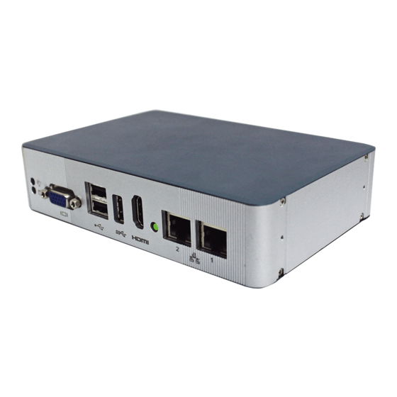
Getting Started 2.2. Take A Tour The computer has some I/O ports, status LED light and controls on the front and rear panels. The following illustrations show all the components called out for IEC-3300. Front View PWR LED HDMI USB 3... - Page 20 Getting Started Rear View Antenna Hole POWER SW USB 1 AUDIO DC IN - 10 -...
-
Page 21: Driver Installation Notes
2.3. Driver Installation Notes The IEC-3300 supports Windows 7 and Windows 8.1. Find the necessary drivers on the CD that comes with your purchase. For different OS, the driver/ utility installation may vary slightly, but generally they are similar. Find the drivers on CD by the following paths:... - Page 22 This page is intentionally left blank. - 12 -...
-
Page 23: Chapter 3 - System Configuration
Chapter 3 System Configuration Chapter 3 - System Configuration - 13 -... -
Page 24: Board Layout
System Configuration 3.1. Board Layout The engine of the computer is the main board. This section will provide an thorough view. 3.1.1. Main Board Board Top 72 74 71 73 - 14 -... - Page 25 System Configuration Board Bottom - 15 -...
-
Page 26: Jumper & Connectors
System Configuration 3.2. Jumper & Connectors The main board comes with some connectors to join some devices and some jumpers to alter hardware configuration. The power board also comes with some connectors. The following in this chapter will explicate each of these components. - Page 27 System Configuration JBAT1 Function: Clears/keeps CMOS Jumper Type: 2.00 mm pitch 1x3-pin header Setting: Description 1-2 Keeps CMOS (default) 2-3 Clears CMOS Board Top 72 74 71 73 JBAT1 - 17 -...
-
Page 28: Connectors
System Configuration 3.2.2 Connectors This section will guide you through the connectors on the main board. LAN1, 2 Function: Ethernet connectors Connector Type: RJ-45 connector that supports 10/100/1000Mbps fast Ethernet Pin Assignment: Pin Description Pin Description MDI0+ MDI0- MDI1+ MDI1- MDI2+ MDI2- MDI3+... - Page 29 System Configuration Reset Function: Reset button Front Panel PWR LED HDMI USB 3 Storage USB 2 Reset HDMI Function: HDMI connector Connector Type: 19-pin HDMI connector with flange Pin Assignment: The pin assignments conform to the industry standard. Front Panel PWR LED HDMI USB 3...
- Page 30 System Configuration USB 3.0 Function: USB 3.0 connector Connector Type: USB 3.0/2.0 type-A connectors Pin Assignment: The pin assignments conform to the industry standard. Front Panel PWR LED HDMI USB 3 Storage USB 2 Reset - 20 -...
- Page 31 System Configuration USB 2.0 Function: Double-stacked USB connectors Connector Type: Two USB 2.0/1.0 type-A connectors Pin Assignment: The pin assignments conform to the industry standard. Front Panel PWR LED HDMI USB 3 Storage USB 2 Reset - 21 -...
- Page 32 System Configuration Function: Analog RGB connector Connector Type: D-Sub 15-pin female connector Pin Assignment: Description. Pin Description GREEN 10 GND BLUE 11 N/C 12 D-DATA 13 H-SYNC 14 V-SYNC 15 D-DCLK Front Panel PWR LED HDMI USB 3 Storage USB 2 Reset - 22 -...
- Page 33 System Configuration USB1 Function: USB 2.0 connector Connector Type: USB 2.0/1.0 type-A connectors Pin Assignment: The pin assignments conform to the industry standard. Rear Panel Antenna Hole POWER SW USB 1 AUDIO DC IN - 23 -...
- Page 34 System Configuration COM1 Function: Serial port Connector Type: External 9-pin D-sub male connector The pin assignments conform to the industry standard. Rear Panel Antenna Hole POWER SW USB 1 AUDIO DC IN - 24 -...
- Page 35 System Configuration DC IN Function: 12V adapter in DC jack Center Connector Type: 2.5φ DC jack with nut and washer Description Center Inner Inner circle Circle Rear Panel Antenna Hole POWER SW USB 1 AUDIO DC IN AUDIO Function: Line_out Rear Panel Antenna Hole POWER SW...
- Page 36 System Configuration Function: Mini-card socket Connector Type: Onboard 0.8mm-pitch 52-pin edge card connector 51 52 The pin assignments conform to the industry standard. Board Bottom - 26 -...
- Page 37 System Configuration mSATA1 Function: mSATA socket Connector Type: Onboard 0.8mm pitch 52-pin edge card connector 51 52 The pin assignments conform to the industry standard. Board Bottom - 27 -...
- Page 38 This page is intentionally left blank. - 28 -...
-
Page 39: Chapter 4 - Installation And Maintenance
Chapter 4 Installation and Maintenance Chapter 4 - Installation and Maintenance - 29 -... -
Page 40: Install Hardware
Installation & Maintenance 4.1. Install Hardware The IEC-3300 is constructed based on modular design to make it easy for users to add hardware or to maintain the computer. The following sections will guide you to the simple hardware installations for the computer. -
Page 41: Restore The Upper/Bottom Cover
Installation & Maintenance The inside of the computer comes to view. Upper side Bottom side 4.1.2. Restore the upper/bottom cover Restore the upper/bottom cover with the box. Upper cover Bottom cover Fasten the screws on sides to complete the assembly. Upper cover Bottom cover - 31 -... -
Page 42: Install Memory Module
Installation & Maintenance 4.1.3. Install Memory Module The main board has one dual inline memory module (DIMM) socket. Load the computer with a memory module to make the computer run programs. The memory module for the computer’s SO-DIMM socket should be a 204-pin DDR3 with a “key notch”... - Page 43 Installation & Maintenance To prevent from interfering during installation, unplug the power connector. Confront the memory module’s edge connector with the SO-DIMM slot connector. Align the memory module’s key notch at the break on the SO- DIMM slot connector. memory SO-DIMM slot module’s key connector's...
- Page 44 Installation & Maintenance Press down the memory module until it is auto-locked in place. Plug the power connector into the socket. - 34 -...
-
Page 45: Wall-Mount
4.1.4. Wall-Mount Fix the wall-mount kit on the both side of device with screws. Find the cutouts marked in the illustration below. Mount the computer to a wall by the said cutouts. - 35 -... - Page 46 This page is intentionally left blank. - 36 -...
-
Page 47: Chapter 5 - Bios
Chapter 5 BIOS Chapter 5 - BIOS - 37 -... - Page 48 BIOS The BIOS Setup utility for the computer is featured by American Megatrends Inc to configure the system settings stored in the system’s BIOS ROM. The BIOS is activated once the computer powers on. When the computer is off, the battery on the main board supplies power to BIOS RAM.
- Page 49 BIOS Key Commands The BIOS Setup utility relies on a keyboard to receive user’s instructions. Hit the following keys to navigate within the utility and configure the utility. Keystroke Function ← → Moves left/right between the top menus. ↓ ↑ Moves up/down between highlight items.
-
Page 50: Main
BIOS 5.1. Main The Main menu features the settings of System Date and System Time and displays some BIOS info and system info. The BIOS info displayed are: Info Description BIOS Version Delivers the computer’s BIOS version. Project name Delivers the name of the project Delivers the date and time when the BIOS Setup utility was Build Date and Time created/updated. -
Page 51: Advanced
BIOS 5.2. Advanced Access the Advanced menu to manage the computer’s system configuration including the Super IO chip. The featured settings and submenus are: Setting Description Boot Configuration 5.2.1. Boot Configuration on page 42 PCI Express Configuration See 5.2.2. PCI Express Configuration on page 42 USB Configuration 5.2.3. -
Page 52: Boot Configuration
BIOS 5.2.1. Boot Configuration Setting Description Numlock Select Power-on state for Num lock 5.2.2. PCI Express Configuration Configures PCI Express by the following settings: Setting Description PCI Express Root Port 4 Enables/disables this PCIe port. PCIe Speed Options are: Auto, Gen 1, Gen 2 Auto is the default. -
Page 53: Usb Configuration
BIOS 5.2.3. USB Configuration Select this submenu to view the status of the USB ports and configure USB features. The featured settings are: Setting Description XHCI Pre-Boot Mode Support Enables/Disables XHCI Pre-Boot mode support Set the mode of operation of xHCI controller xHCI Mode Options are Disabled/Enabled/Auto/Smart Auto(default) -
Page 54: Sata Configuration
BIOS 5.2.4. SATA Configuration Select this submenu to configure the SATA controller and HD. Setting Description Enables/disables the present SATA controller. SATA Controller(s) Enabled is the default. SATA Test Mode Enables/disables the SATA test mode. Configures how to sun the SATA drives. Configures SATA Mode Options available are AHCI (default) and IDE. -
Page 55: Acpi Table/Feature Control
BIOS 5.2.5. ACPI Table/Feature Control Setting Description FACP - RTC S4 This function will be avalible only when ACPI is enabled. Wakeup Enables/disables S4 Wakup from RTC. This item is valid only for WIN2K and WINXP. Also, a frech APIC - IO APIC Mode install of the OS must occur when APIC mode is desired. -
Page 56: Security
BIOS 5.3. Security The Security menu sets up the TPM (Trusted Platform Module) device and password for the system’s administrator account. Once the administrator password is set up, this BIOS Setup utility is limited to access and will ask for the password each time any access is attempted. -
Page 57: Power
BIOS 5.4. Power The Security menu sets up the password for the system’s administrator account. Once the administrator password is set up, this BIOS Setup utility is limited to access and will ask for the password each time any access is attempted. -
Page 58: Boot
BIOS 5.5. Boot The Boot menu configures how to boot up the system such as the configuration of boot device priority. The featured settings are: Setting Description Select Boot Type. Options Legacy Boot Boot Type Type(default) and UEFI Boot Type Allow InsydeH20 to Skip certain tests while booting . -
Page 59: Exit
BIOS 5.6. Exit The Save & Exit menu features a handful of commands to launch actions from the BIOS Setup utility regarding saving changes, quitting the utility and recovering defaults. The features settings are: Setting Description Exit Saving Changes Saves the changes and quits the BIOS Setup utility. Save Changes Without Exit Save Changes but does not quit the BIOS. - Page 60 This page is intentionally left blank. - 50 -...
-
Page 61: Appendices
Appendices Appendices - 51 -... -
Page 62: Appendix A: Install Msata Storage
BIOS Appendix A: Install mSATA Storage To install an mSATA storage module to the computer: Remove the top cover from the computer as described in 4.1.1. Open the on page 30. upper/bottom cover of the Computer The inside of the computer comes to view. Find the socket for mSATA module as the picture above shows. - Page 63 BIOS Fully plug the module until it cannot be plugged any more. Connector break Fully plug the module. Press the module down and fix the module in place using two screws. Restore the upper cover to the computer. Fasten the screws on sides to complete the assembly. - 53 -...
-
Page 64: Appendix B: Wi-Fi Module Wifi-At2200 Hardware Installation
BIOS Appendix B: Wi-Fi Module WIFI-AT2200 Hardware Installation To use Wi-Fi, hardware-wise the computer needs a Wi-Fi module installed, and software-wise the computer needs the device driver and an application program. This appendix will guide you to install the Wi-Fi module WIFI-AT2100 and the device driver. - Page 65 BIOS Prepare the WIFI-AT2100 Wi-Fi module kit. The module is a half-size module of PCI Express Mini-card form factor, with two U.FL connectors, one is “MAIN“, and the other is “AUX“. Two U.FL connectors, one is “MAIN”, the other is “AUX”. Plug the Wi-Fi module to the socket’s connector by a slanted angle.
- Page 66 Appendices Press the module down and fix the module in place using two screws. Remove a plastic plug from the computer's rear (or front) panel to make an antenna hole. Keep the plastic plug for any possible restoration in the future.
- Page 67 Appendices Connect the RF antenna’s MHF connector to the Wi-Fi module’s “MAIN“ connector. Connect the RF antenna’s MHF connector to the Wi-Fi module’s “MAIN” connector From the other end of the RF antenna, which is an SMA connector, remove the washer and the nut. Save the washer and nut for later use. Note the SMA connector has the form of a threaded bolt, with one flat side.
- Page 68 Appendices 11. Mount the washer first and then the nut to the SMA connector. Make sure the nut is tightened. Mount the washer and the nut to the SMA connector. Tighten the nut. 12. Restore the computer's bottom cover and fasten the screws 13.
Need help?
Do you have a question about the IEC-3300 and is the answer not in the manual?
Questions and answers