
Related Manuals for CAME G2080EZC


Summary of Contents for CAME G2080EZC
- Page 1 Automatic barriers FA01283-EN - GARD 8 series English G2080EZC INSTALLATION AND OPERATION...
-
Page 2: Read Carefully
• Employ this product only for the use for which it was expressly made. Any Frequently check the system for any malfunctions or signs of wear and tear other use is dangerous. CAME S.p.A is not liable for any damage caused by or damage to the moving structures, to the component parts, all anchoring improper, wrongful and unreasonable use •... -
Page 3: Reference Regulations
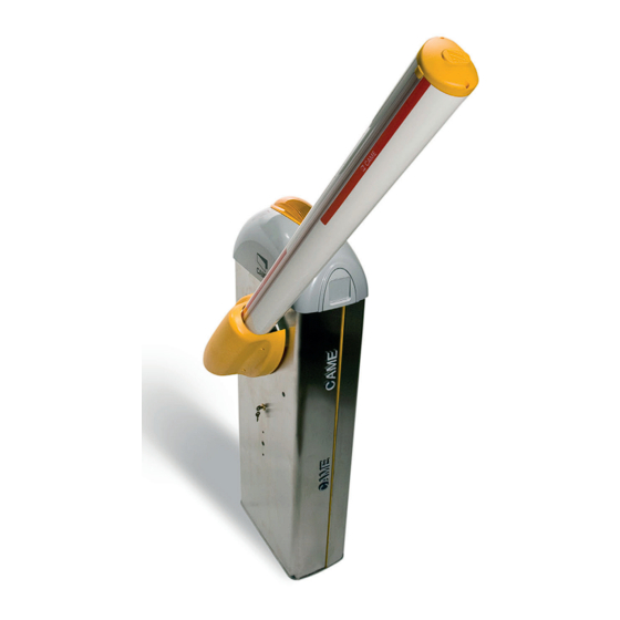
☞ This symbol shows which parts to tell users about. REFERENCE REGULATIONS Came S.p.A. the company is quality and environmentally certified by the ISO 9001 and the ISO 14001 respectively, for its management systems. This product complies with the current regulations mentioned in the declaration of conformity. - Page 4 Description of parts 1. Dome 10. Boom adjustment buffer 2. Motor-shaft plate 11. Transmission rod 3. Mid plate 12. Gearmotor with encoder 4. Boom-attachment cover 13. Inspection hatch 5. Protective casing shear proof 14. Anchoring plate 6. Cabinet 15. Anchoring bracket 7.
- Page 5 CAME GENERAL INSTRUCTIONS FOR INSTALLING ⚠ Only skilled, qualified staff must install this product. Important! Using original CAME control and safety devices and accessories ensures easy installation and system maintenance. Preliminary checks ⚠ Before beginning, do the following: • make sure the plate is anchored to a solid spot;...
-
Page 6: Installation
Control and safety devices 2 x 0.5 mm Antenna RG58 max 10 m Paired or CRP (Came Remote Protocol) UPT CAT 5 max 1000 m Metal mass detector (see product literature) If cable lengths diff er from those specifi ed in the table, establish the cable cross-sections according to the actual power draw of the connected devices and in compliance with regulation CEI EN 60204-1. - Page 7 Set up a foundation frame that is larger than the anchoring plate and sink it into the dug hole. Fit an iron cage into the foundation frame to reinforce the concrete. Assemble the four anchoring brackets to the anchoring plate. Place the plate over the iron cage.
- Page 8 Preparing the barrier Fit the key into the lock and turn it counter clockwise , lift the dome and remove the inspection hatch ⚠ Warning! The barrier is set up for installing on the left. When installing on the right, invert the boom's opening direction, as follows: ...
- Page 9 Installing the barrier The cabinet should be installed with the inspection hatch on the most accessible side to make any adjusting easier. Place the cabinet onto the anchoring plate and fasten it using nuts and washers. Assemble the boom-attaching cover, the mid plate and motor-shaft plate with a screw. Leave the screw loose to then facilitate fitting the boom. Fit the boom into the boom-attachment cover and fasten it using the screws.
- Page 10 Fit the anti-shearing protective cover onto the boom-attachment cover and fasten it with screws. UNI6954 Ø 3.9x19 Balancing the boom Before balancing the boom, check on the table below for congruences between the chosen spring, accessories and passage clearance. 400 mm PASSAGE CLEARANCE (max.
- Page 11 Release the gearmotor and position the boom vertically. Lock the gearmotor again. Install the spring into the barrier in the following way: - fit a UNI5739 M12x70 screw into the attachment bracket and tighten the UNI5588 M12 nut to the screw . - tighten the screw into the spring ;...
-
Page 12: Electrical Connections
ELECTRICAL CONNECTIONS ⚠ Warning! Before working on the control panel, cut off the main current supply and, if present, remove any batteries. Power supply to control panel and control devices: 24 V AC/DC. Functions on input and output contacts and time and user management details, are set up and viewable on the control panel's display. All connections are quick-fuse protected. - Page 13 Power supply EMC01 filter 230 V AC - 50/60 Hz Blue Orange Transformer Ferrite White 24V 0 THERMAL Terminals for powering up accessories: - a 24 V AC normally; - a 24 V DC when the emergency batteries are operating; Overall allowed power: 40 W...
- Page 14 Factory wiring The gearmotor is already connected. To install the barrier on the right, follow the instructions in the PREPARING THE BARRIER. 24 V DC gearmotor with encoder Brown Blue Ferrite White Brown Green Warning devices Barrier indicator light (contact rated for: 24 V AC - 3 W max). It warns of the barrier status, see function F 10.
- Page 15 Command and control devices Black Transponder or card reader Blue White Keypad selector OPEN-CLOSE-INVERT function (step-step) from control device (NO contact). ONLY CLOSE function from control device (NO contact). Warning: in MAINTAINED ACTION mode, the control device must be connected to 2-4. Warning! OPEN ONLY function from control device with NO contact.
- Page 16 Safety devices Configure contact CX or CY (NC), input for safety devices such as Photocells Photocells DELTA-S photocells. See CX input functions (Function F2) or CY (Function F3)- C1 reopening while closing. When the boom is closing, opening the contact causes its movement to invert until fully opened;...
- Page 17 10 11 E1 E6 Rx Tx 1 2 3 3P 4 5 7 CX CY Connection with Came Remote Protocol (CRP) and for either paired or alternate operating mode Serial RS485 connection to home automation system or for either paired or A B GND alternate barrier operating mode.
- Page 18 Establishing the endstop points Close the inspection hatch and power up the system. Activate the barrier to check whether the boom is parallel to the road surface when closed and at about 89° when open. ⚠ The boom's opening and closing maneuvers must be performed with the inspection hatch closed. To correct the boom's vertical position: - lower the boom;...
- Page 19 PROGRAMMING ⚠ During programming, the barrier must not be moving. Description of programming commands Display S1 GND The ENTER key is for: The ESC button is for: - entering menus; - exiting menus; - confirming or memorizing set values. - deleting changes. The <...
- Page 20 Functions map Total stop function (1-2) Function associated to input CX Function associated to input CY Safety test function Maintained action function Obstruction detection with motor idle function F 10 Warning light function F 11 Encoder exclusion F 14 Sensor type selection function F 15 Intermittent luminous cord function F 18...
- Page 21 Safety test 0 = Deactivated (default) / 1 = CX / 2 = CY / 3 = CX+CY After every opening or closing command, the board will check whether the photocells are working properly. Maintained action 0 = Deactivated (default) / 1 = Activated The barrier opens and closes by keeping one button pressed.
- Page 22 This function appears only if function F 49 is set to either PAIRED or ALTERNATE. Peripheral number 1 ----> 225 With systems fitted with several operators and the CRP (Came Remote Protocol) system connection, set an address between 1 and 225 for each control panel. Sleep Mode To reduce the amount of energy consumed by the stand-by photocells.
- Page 23 U 1 Entering a user 1 = Step-step command (open-close) / 2 = Sequential command (open-stop-close-stop) / 3 = Open only command / 4 = Partial command / 5 = contact B1-B2 output Up to a maximum of 25 users can be entered and each can be associated to a function of choice among those available. Entering is done via transmitter or other control device (see ENTERING USERS AND ASSOCIATED COMMANDS).
- Page 24 Travel calibration Before doing a travel calibration, establish the boom type, check that the boom is balanced and that the maneuvering area is free of obstructions. Important! While calibrating, all of the safety devices will be disabled excluding the TOTAL STOP one. 1.
- Page 25 When entering/deleting users, the fl ashing numbers that appear, are numbers that can be used for other users you may wish to enter (maximum 25 users). Entering a user with an associated command User Associated command 1. Select U 1. Press ENTER to confirm.
-
Page 26: Final Operations
Memory Roll Card To memorize user data and configure the system, to then reuse them with another control board even on another system. Memory roll FINAL OPERATIONS When you done with the electrical connections and setting up, fit the control panel cover and fasten it with the screws . Replace the inspection hatch and upper dome . - Page 27 Connect the two control panels via a CAT 5 type-cable (max 1,000 m) to terminals A-A / B-B / GND-GND, see paragraph on CONNECTING WITH THE CAME REMOTE PROTOCOL (CRP) AND FOR PAIRED OR ALTERNATE OPERATING MODE. Connect all of the control and safety devices to the MASTER control panel.
-
Page 28: Alternate Connection
Connect the two control panels via a CAT 5 type-cable (max 1,000 m) to terminals A-A / B-B / GND-GND, see paragraph on CONNECTING WITH THE CAME REMOTE PROTOCOL (CRP) AND FOR PAIRED OR ALTERNATE OPERATING MODE. Connect all of the control and safety devices to the MASTER control panel. -
Page 29: Error Message
ERROR MESSAGE The error messages appear on display and are notified by LEDs The boom travel calibration was interrupted by the activation of the STOP button. Encoder is broken. Services test error. Insufficient working time Maximum number of obstructions detected. Transformer overheating. -
Page 30: Maintenance Log
MAINTENANCE LOG Periodic maintenance ☞ Before doing any maintenance, cut off the power supply, to prevent any hazardous situations caused by accidental boom movements. Periodic maintenance log kept by users (every six months) Date Notes Signature Extraordinary maintenance ⚠ The following table is for logging any extraordinary maintenance jobs, repairs and improvements performed by specialized contractors. ... -
Page 32: Dismantling And Disposal
☞ CAME CANCELLI AUTOMATICI S.p.A. employs a certified Environmental Management System at its premises, compliant with the UNI EN ISO 14001 standard to ensure the environment is safeguarded. Please continue safeguarding the environment. At CAME we consider it one of the fundamentals of our operating and market strategies. Simply follow these brief disposal guidelines:...
Need help?
Do you have a question about the G2080EZC and is the answer not in the manual?
Questions and answers