Goodwe A-ES Series User Manual
Hybrid inverter
Hide thumbs
Also See for A-ES Series:
- User manual (52 pages) ,
- Quick installation manual (26 pages) ,
- Quick installation manual (2 pages)
Table of Contents
Advertisement
Advertisement
Table of Contents

Subscribe to Our Youtube Channel
Related Manuals for Goodwe A-ES Series


Summary of Contents for Goodwe A-ES Series
- Page 1 StorageGo APP SEMS Portal APP SEMS Portal website LinkedIn Company's www.semsportal.com offical website A-ES SERIES USER MANUAL JIANGSU GOODWE POWER SUPPLY TECHNOLOGY CO.,LTD No. 90 Zijin Rd., New District, Suzhou, 215011, China HYBRID INVERTER www.goodwe.com service@goodwe.com For North America...
-
Page 2: Table Of Contents
TABLE OF CONTENTS INTRODUCTION 1.1 Operation Modes Introduction ..................01 1.2 Safety & Warning ........................ 02 1.3 Product Overview ......................06 1.4 User Interface Introduction ....................07 INSTALLATION INSTRUCTION 2.1 Unacceptable Installation ....................08 2.2 Packing List .......................... 08 2.3 Mounting ..........................09 2.3.1 Select Mounting Location .................. -
Page 3: Introduction
The AES series, also called hybrid or bidirectional solar inverters, can be applied to solar system after known as Goodwe) has been designed and tested in accordance with necessary safety with participation of PV, battery, loads and grid system for energy management. Energy requirement. - Page 4 The input and output circuits are isolated from the enclosure and that system grounding, if required by Sections 690.41, Before connecting the A-ES series inverter to the AC distrubution grid, approval must be received by the appropiate local 690.42 and 690.43 of the National Electric Code, ANSI/NFPA 70, is the responsibility of the installer.
-
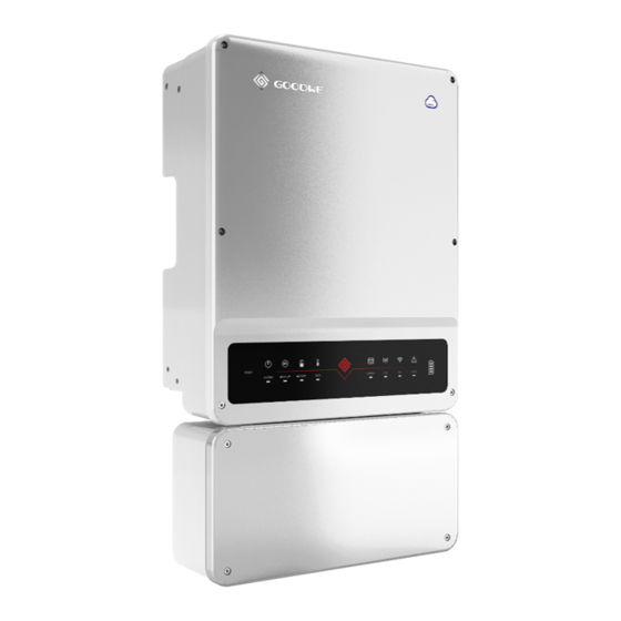
Page 5: Product Overview
PV non solé. WiFi Module A transmitter which meets the SUNSPEC protocol has integrated in A-ES series energy storage inverters. Already complet- ed tests in CSA laboratory and obtained certifications. It can be compatible with the Rapid Shut-Down device in the market that complies with SUNSPEC protocol, together to accomplish system that meets the requirements of NEC2017 [1] DC switch: DC switch is used to shut down the PV system in case of emergency. -
Page 6: User Interface Introduction
1.4 User Interface Introduction INSTALLATION INSTRUCTIONS 2.1 Unacceptable Installations Please avoid the following installations, which will damage the system or the Inverter. Following installations should be avoided. Or any damage caused will not be covered by Goodwe RESET warranty policy. SYSTEM... -
Page 7: Mounting
500mm WiFi Configuration Instruction www.goodwe.com Version 1.1.1 Quick Installation WiFi Configuration Cap Removal Tool Straight Screwdriver User Manual Instructions Instruction Upward---------- 500mm 200mm Downward------ 300mm 300mm 200mm 2.3 Mounting Front------------- 300mm Both sides------- 200mm 2.3.1 Select Mounting Location For inverter's protection and convenient maintenance, mounting location for inverter should be... -
Page 8: Conduit Wiring And Installation
Avoid drilling holes in walls which with cables inside or on the back. L’ unité de connexion ne peut pas soulever la tenue. WARNING! Make sure the hole positions are horizontal and vertical. Évitez de tenir et de soulever l’ unité de connexion, de maintenir AVERTISSEMENT!... -
Page 9: Wiring Box Conduit Plugs
comply with all US National Electric Code (NEC) requirement and Step 2 DANGER! local AHJ inspector requirements in the Unite States. Meanwhile in DANGER! Canada method and process must comply with Canadian Electric Remove the waterproof cover Code: Part I and Part II, and the local AHJ inspector requirements. by a cap removal tool. - Page 10 The polarity of PV strings cannot be connected reversely, otherwise Minimum isolation resistance Inverter model DANGER! the inverter could be damaged. DANGER! GW5000A-ES 600kΩ Do not connect multiple PV inputs in parallel. If required, add a fuse 500kΩ GW6000A-ES outside or a breaker which observes safety specification. 430kΩ...
-
Page 11: Battery Wiring Connection
2.4.3 Battery Wiring Connection • Assurez-vous que l’ interrupteur de la batterie est éteint et que la tension de la batterie en circuit ouvert est toujours inférieure ou Please follow the requirements and steps below strictly, or A-ES WARNING! égale à 500 V DC. damage or even fire may occur if not satisfied with next conditions. -
Page 12: On-Grid Connection
Make sure the inverter is totally isolated from any DC or AC power Step 2 DANGER! before connecting AC cable. DANGER! Drag the battery cables through battery port Assurez-vous que l’ onduleur est totalement isolé de toute puissance DC ou AC avant de connecter le câble AC. Connect battery cables to battery terminals. -
Page 13: Back-Up Connection
In case of systems not connected to the batteries, the back-up Make sure the inverter is totally isolated from any DC or AC power DANGER! function is strongly not advised to use. GoodWe shall not cover the standard warranty and be before connecting back-up cable. DANGER! liable for any consequences arising from users not following this instruction. - Page 14 Back-up Load Configuration Back-up wiring connection process To reduce the risk of fire, do not connect to an AC load center (circuit WARNING! breaker panel) having multi wire branch circuits connected. AVERTISSEMENT! Pour réduire le risque d’ incendie, ne vous connectez pas à un centre de chargement AC (panneau de disjoncteur) ayant des circuits de branche multi-fil connectés.
-
Page 15: Auto-Transformer Connection (Optional)
2.4.6 Auto-transformer Connection (Optional) The auto-transformer is small in size, but very heavy. It is recommend- CAUTION! ed that two people carry it during installation. Wall mounted bracket and equipment installation PRUDENCE! L’ auto-transformateur est de petite taille, mais très lourd. Il est After the auto-transformer installed, off-grid functions can be used only, otherwise back-up recommandé... -
Page 16: Ct Connection
Step 3 Step 5 Pass the corresponding conduit and fasten NTC of auto-transformer use the cable 22AWG the joint. or 24AWG, 600V insulated. One end is connect- ed with a 2-pin terminal for inside inverter Cross the cables athrough the auto-trans- connection, and the other end is pressed with former port. -
Page 17: Battery Bms Connection
Step 1 Step 2 Connect CT1 and CT2 in the Drag the cables through BMS port. accessories to the corresponding Connect cables to BMS port. line at the entrance. Grid Power Meter CT 2 CT 1 CT 1 connect to L1 CT 2 connect to L2 Load Step 2... -
Page 18: Wifi Communication Connection
2.5 StorageGo App necessary to detect and terminate the arc by shutting down the inverter. The AFCI function is integrated in the A-ES series inverter. Once an arc is detected, the StorageGo is an external monitoring/ configuration application for VIRGIN... -
Page 19: System Connection Diagram
2.7 System Connection Diagram This diagram is an example for US Split grid system. Wiring Box Of GoodWe AES Series Hybrid Inverter 1'' Conduit 1'' Conduit 1'' Conduit 1 '' Conduit 1'' Conduit L2 N L2 N L2 N *Note 3... -
Page 20: Wiring System
2.8 Wiring System Grid Power meter Main breaker RESET SYSTEM BACK-UP BATTERY GRID ENERGY Wi-Fi FAULT Meter CT Communication AC Breaker Load AC output breaker Back-up output breaker 120V 240V Loads Loads Battery Auto-transformer PV Strings... -
Page 21: Others
OTHERS 3.1 Error Messages The error messages below will be displayed on StorageGo App or reported by e-mail if an error occurs. ERROR MESSAGE EXPLANATION REASON SOLUTIONS 1. Check (use multi-meter) if AC side has voltage . Make sure grid power is available. Public grid power is not available (power Utility Loss Inverter does not detect the connection of grid... -
Page 22: Troubleshootings
3.2 Troubleshootings 4. Check on App whether the charge time has already been set, as during charge time, battery will not discharge (battery will charge in priority during coincident time of charge/discharge). Checking As Start AES Up And Turn On AC Power Battery does not charge when PV power higher than load power Battery settings, BMS communication and safety country: Param... - Page 23 CT Q: Which battery should I use for AES? A: For A-ES series inverter, it could connect lithium batteries which have compatibility with A-ES Q: What is the maximum current allowed to go through CT on Smart Meter? series inverter with nominal voltage from 80V to 495V.
-
Page 24: Disclaimer
3.3 Disclaimer 3.4 Technical Parameters 3.4.1 Inverter Specification The AES series inverters are transported, used and operated under environmental and electrical conditions. Manufacturer has the right not to provide after-sales services or assistance under Technical Data GW5000A-ES GW6000A-ES GW7000A-ES following conditions: Battery Input Data •... - Page 25 Technical Data GW5000A-ES GW6000A-ES GW7000A-ES Technical Data GW7600A-ES GW8600A-ES GW9600A-ES Protection Battery Input Data Insulation Resistor Detection Integrated Battery Type Li-Ion Residual Current Monitoring Unit Integrated Battery Voltage Range (V) 80~495 Output Over Current Protection Integrated Max. Charging Current (A) Back-up Output Short Protection Integrated Max.
-
Page 26: Auto-Transformer Specification
3.4.2 Auto-transformer Specfication Technical Data GW7600A-ES GW8600A-ES GW9600A-ES Protection Technical Data Insulation Resistor Detection Integrated Rated Voltage (Vac) 120/240V Split Phase Residual Current Monitoring Unit Integrated Rated Frequency (Hz) Output Over Current Protection Integrated Max Continuous Output Current Per Phase @ 120 V (A) Back-up Output Short Protection Integrated Split Phase Imbalance Current @Rated Power (A) -
Page 27: Maintenance
3.5 Maintenance 3.5.2 Fuse Replacement These servicing instructions are for use by qualified personnel only. If the inverter fuses are broken, replace them quickly. Before the replacement, all the power (PV, WARNING! To reduce the risk of electric shock, do not perform any servicing battery, AC) connected by A-ES must be turned off. -
Page 28: Inverter Replacement
Step 5 Step 3 Remove 4 screws . Remove the 4 cover screws by Allen Wrench. Remove the broken fuses which is shown Remove the cover. in the right figure and repalce them. Fasten the screws. 3.5.3 Inverter Replacement Step 4 When the inverter needs to be dismantled, separate the upper and lower boxes according to the Remove 5 screws by cross screwdriver. -
Page 29: About Periodical Maintenance
Step 7 Step 11 Lift the upper machine to separate the upper and lower boxes. Install the black plastic board. Fasten 5 screws by cross screwdriver. Step 8 Step 12 Fasten 4 screws from the outside of the Move the replacement machine down to inverter. - Page 30 Appendix protection category defintion Overvoltage category definition Applies to equipment connected to a circuit where measures have been Category I taken to reduce transient overvoltage to a low level. Applies to equipment not permanently connected to the installation. Category II Examples are appliances, portables tools and other plug-connected equipment.
Need help?
Do you have a question about the A-ES Series and is the answer not in the manual?
Questions and answers