Goodwe A-ES Series User Manual
Hide thumbs
Also See for A-ES Series:
- User manual (30 pages) ,
- Quick installation manual (26 pages) ,
- Quick installation manual (2 pages)
Table of Contents
Advertisement
Advertisement
Table of Contents

Subscribe to Our Youtube Channel
Related Manuals for Goodwe A-ES Series


Summary of Contents for Goodwe A-ES Series
- Page 1 User Manual Hybrid Inverter A-ES Series V1.6-2022-01-05...
-
Page 2: Table Of Contents
Content User Manual V1.6-2022-01-05 TABLE OF CONTENTS 01 Introduction .............. 1 1.1 Operation Modes Introduction ..............1 1.2 Safety and Warning ...................2 1.3 Product Overview ..................6 1.4 User Interface Introduction ..............7 02 Installation Instructions ..........8 2.1 Unacceptable Installations ...............8 2.2 Packing List ....................9 2.3 Mounting ....................9 2.3.1 Select Mounting Location ................. - Page 3 User Manual V1.6-2022-01-05 Content 03 OTHER ..............33 3.2 Troubleshooting ..................35 3.3 Disclaimer ....................38 3.4 Technical Parameters ................39 3.4.1 Inverter Specification ..................39 3.4.2 Auto-transformer Specfication...............43 3.4.3 Grid Parameter Setting ..................43 3.5 Maintenance ....................44 3.5.1 Clearing and Replacing Fans ................44 3.5.2 Fuse Replacement ...................45 3.5.3 About Periodical Maintenance ...............46 Appendix ..............
-
Page 4: Introduction
User Manual V1.6-2022-01-05 01 Introduction The A-ES series, also called hybrid or bidirectional solar inverters, provides energy management in a PV system that includes solar modules, a battery, loads, and utility grid connection. Energy produced by the PV system is prioritized to supply loads and then any excess energy to charge the battery. -
Page 5: Safety And Warning
01 Introduction 1.2 Safety and Warning A-ES series Hybrid inverter has been designed and tested in accordance with safety requirement. As with power electronic devices, there are residual risks despite strict standards. You are recommended to read the following information carefully to prevent personal injury and property damage. - Page 6 01 Introduction User Manual V1.6-2022-01-05 Fragile - The package/product should be handled carefully and never be tipped over or slung. Fragile - L’emballage/produit doit être manipulé avec soin et ne jamais être renversé ou en bandoulière. Refer to the operating instructions. Consultez les instructions d’exploitation.
- Page 7 A (avec courant d’exploitation de 30mA) peut être utilisé si nécessaire. Before connecting the A-ES series inverter to the AC distrubution grid, approval must be received by the appropiate local utility as required by national and state interconnection regulations.
- Page 8 L’onduleur n’est pas équipé d’un transformateur d’isolement et est destiné à être installé par NFPA 70, 690,35 avec un tableau PV non solé. A transmitter meeting the SUNSPEC protocol is integrated in A-ES series inverters and has obtained CSA certification. It is compatible with Rapid Shut-Down devices in the marketplace that comply with the SUNSPEC protocol;...
-
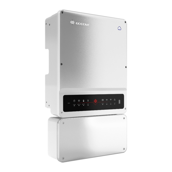
Page 9: Product Overview
RSD (remote shutdown) switch. [2] AC bypass switch. It is optional for A-ES series inverter. It is allowed to be used to "bypass" inverted power when the inverter is not working so that the backup load can get power from the utility grid. -
Page 10: User Interface Introduction
01 Introduction User Manual V1.6-2022-01-05 1.4 User Interface Introduction RESET SYSTEM BACK-UP BATTERY GRID ENERGY Wi-Fi FAULT Wi-Fi reset & reload Wi-Fi reset means restarting Wi-Fi module. Wi-Fi settings will be reprocessed and saved automatically. Wi-Fi Reload means setting Wi-Fi module back to default factory setting. Wi-Fi reset Wi-Fi reload Short press reset button. -
Page 11: Installation Instructions
Back-up Back-up On-grid Load No parallel connection of the back-up is allowed Single PV string cannot be connected to multipe in general application. Please contact GoodWe inverters. first for advanced application. Generator Back-up Battery Battery Single battery bank cannot be connected to On-Grid or back-up side cannot be connected to multiple inverters. -
Page 12: Packing List
02 Installation Instructions User Manual V1.6-2022-01-05 2.2 Packing List Upon receiving the hybrid inverter, please check if any of the components as shown below are missing or broken. The colored wire ferrules provided in the accessory kit are to be used in making clean and solid wire to terminal connections. -
Page 13: Wall Mounted Bracket And Inverter Installation
User Manual V1.6-2022-01-05 02 Installation Instructions Keep away Keep it clear Keep dry Rain Accmulated snow from sunlight of snow Rule 6. Inverter should be installed at eye level for convenient maintenance. Rule 7. Product label on inverter should be clearly visible after installation. Do not damage the lable. - Page 14 02 Installation Instructions User Manual V1.6-2022-01-05 (7.56 in.) 192mm 415mm (16.34 in.) (6.89 in.) 175mm Step 1 (4.33 in.) ( 4.72 in.) 110mm 120mm Take out the mounting template which is to locate the hole position of the wall mounted brackets. 120mm Fix the mounting template on the wall (4.72 in.)...
- Page 15 User Manual V1.6-2022-01-05 02 Installation Instructions Step 2 Use expansion bolts in accessory box to fix the wall-mounted bracket onto the wall tightly. Wall -mounted bracket Expansion bolts (4.33 in.) (4.72 in.) 110mm 120mm 120mm (4.72 in.) 70mm 70mm (2.76 in.) (2.76 in.) Bearing capacity of the wall must be higher than 100kg(220.46lb), otherwise it may not be able to prevent the inverter from dropping.
-
Page 16: Conduit And Wiring Installation
02 Installation Instructions User Manual V1.6-2022-01-05 Step 4 Fasten the inverter by fixed screws. (3 positions) Step 5 Inverter can be locked for prevention of thievery. Lock will not be provided by inverter manufacturer. Step 6 DC switch should be in "OFF" position during installation and maintenance. -
Page 17: Wiring Box Conduit Plugs
User Manual V1.6-2022-01-05 02 Installation Instructions (NEC) des États-Unis et aux exigences locales des inspecteurs de l’AHJ dans les États-Unis. Pendant ce temps, au Canada, la méthode et le processus doivent être conformes au Code canadien de l’électricité : partie I et partie II, ainsi qu’aux exigences locales des inspecteurs de l’AHJ. -
Page 18: Pv Wiring Connection
02 Installation Instructions User Manual V1.6-2022-01-05 2.4.2 PV Wiring Connection Before PV wiring connection, please read this section carefully. • The total short-circuit current of PV string must not exceed inverter's WARNING! maximum DC short-circuit current. • Positive and negative poles of PV strings should not be grounded. •... - Page 19 User Manual V1.6-2022-01-05 02 Installation Instructions Step 1 If using stranded wires, select a proper size wire ferrule (included in accessories box) for the PV input circuits. Crimp the wire ferrules onto the conductors tightly. Note: Make sure the cable jacket is not locked within wire...
-
Page 20: Battery Wiring Connection
02 Installation Instructions User Manual V1.6-2022-01-05 Assurez-vous que la ligne de sol de GND est reliée au point de terrassement et à la connexion stable entre le cadre du module PV et le point de terrassement. Do not remove the waterproof bolt from any PV input terminals not being used. - Page 21 User Manual V1.6-2022-01-05 02 Installation Instructions • L’utilisation de fils inappropriés peut causer un mauvais contact et un obstacle élevé, ce qui est dangereux pour le système. N’enlevez pas le boulon imperméable à l’eau des terminaux d’entrée DC si les terminaux d’entrée DC d’A-ES ne sont pas connectés aux chaînes photovoltaïques.
-
Page 22: On-Grid / Ac Connection
02 Installation Instructions User Manual V1.6-2022-01-05 2.4.4 On-Grid / AC Connection An external AC breaker, usually located in a load panel or solar dedicated AC sub-panel, is needed for on-grid / AC connection to isolate the inverter from the utility grid when necessary. Proper specification of an AC circuit breaker for the specific inverter model is advised. -
Page 23: Back-Up Connection
Otherwise, the off-grid function may not be used, and back-up loads may be damaged. 2. For A-ES series inverters, the installation typically consists of the inverter being connected to both PV modules and batteries. In the case of systems not connected to batteries, it is strongly advised not to use the back-up function. - Page 24 Declaration for back-up loads A-ES series hybrid inverters are able to supply overload power output at its Back-Up terminals. For details, please refer to the Technical Parameters in section 3.4. However, this inverter has self- protection derating at high ambient temperature.
- Page 25 User Manual V1.6-2022-01-05 02 Installation Instructions Back-up Connection Make sure the inverter is totally isolated from any DC or AC power before connecting back-up cable. DANGER! Assurez-vous que l’onduleur est totalement isolé de toute puissance DC ou AC avant de connecter le câble de back-up. When using the back-up function of the inverter, corresponding protective devices like AC breaker should be applied to ensure safety or satisfy local requirement.
- Page 26 02 Installation Instructions User Manual V1.6-2022-01-05 Case1. If there is no 240V Load, both 120V Load 1 and Load 2 individually have a total Max power ≤ 5kVA. Case2. If there is only a 240V Load and no 120V loads, inverter output power ≤ 10kVA. Case3.
-
Page 27: Auto-Transformer Connection (Optional)
User Manual V1.6-2022-01-05 02 Installation Instructions Step 2 Run the Back-up conductors (N, L1, L2) through a conduit opening located either below the BACK UP terminals. Connect the Back-up AC conductors to BACK UP terminals. BACK UP 2.4.6 Auto-transformer Connection (Optional) The off-grid functions can be used only after the auto-transformer is installed. - Page 28 02 Installation Instructions User Manual V1.6-2022-01-05 Step 2 Carry the auto-transformer by holding the heatsink on two sides and place the equipment on the mounting bracket. The auto-transformer is small in size, but very heavy. It is recommended that two people carry it during installation. CAUTION! L’auto-transformateur est de petite taille, mais très lourd.
- Page 29 User Manual V1.6-2022-01-05 02 Installation Instructions Step 3 The temperature sensor (‘NTC’) connection to the auto-transformer uses a pair of #22 or #24 AWG, 600V insulated wires. One end connects with a 2-pin ‘A-TX’ terminal inside the inverter, and the other end is crimped with the smallest wire ferrule in the accessory box and connected to the auto-transformer ‘NTC’...
-
Page 30: Ct Connections
02 Installation Instructions User Manual V1.6-2022-01-05 2.4.7 CT Connections The two split-core current transformers (CTs) in product box must be installed for the system to detect AC Mains current direction and magnitude; this data instructs the operation of A-ES inverter based on operating mode. Note: 1. -
Page 31: Battery Bms Connection
2.4.8 Battery BMS Connection There are two serial communication options for the battery BMS (Battery management system) of the A-ES series: - Controller Area Network (CAN) 1 communication (e.g., for BYD battery) - RS-485 communication (‘485 network’) (e.g., for LG battery) Select the corresponding communication according to the battery type installed. -
Page 32: Wifi Communication Connection
Safety Country 50Hz Grid Default 3. Wi-Fi configuration. Battery Type Work Model General Mode Please download "PV Master App" from www.goodwe.com or scan Meter Status Communication failure the QR code on the back of this user manual. BMS Status Communication failure2... -
Page 33: Arc Detection
The AFCI function is integrated in the A-ES series inverter. Once an arc is detected, the corresponding error and time will be reported in the App. The first 4 faults of the inverter within 24 hours can be resolved by automatic recovery or manual recovery. -
Page 34: System Connection Diagram
02 Installation Instructions User Manual V1.6-2022-01-05 2.7 System Connection Diagram Wiring Box Of AES Hybrid Inverter 1 '' Conduit 1'' Conduit L2 N *Note 3 BACKUP Loads Main Distribution L2 N Distribution Panel Panel BACKUP Panel Main Breaker 50A CB *Note 1 50A CB BACKUP Panel... -
Page 35: Wiring System
User Manual V1.6-2022-01-05 02 Installation Instructions 2.8 Wiring System Grid Power Meter Main Breaker Meter CT Communication AC Breaker AC Breaker PV Strings Load Back-up Breaker Battery 120V 240V Loads Loads Auto-transformer Power ON Turn on Power OFF Turn off... -
Page 36: Other
User Manual V1.6-2022-01-05 03 OTHERS 03 OTHER 3.1 Error Messages The error messages below will be displayed on PV Master App or reported by e-mail if an error occurs. ERROR EXPLANATION REASON SOLUTIONS MESSAGE Utility Loss Public grid power Inverter does 1. - Page 37 03 OTHERS User Manual V1.6-2022-01-05 ERROR EXPLANATION REASON SOLUTIONS MESSAGE 1. Use multi-meter to check if the resistance between earth & inverter Isolation failure frame is close to zero. If it's not, please could be caused by ensure that the connection is well. multiple reasons 2.
-
Page 38: Troubleshooting
User Manual V1.6-2022-01-05 03 OTHERS ERROR EXPLANATION REASON SOLUTIONS MESSAGE DC Bus High BUS voltage is Try to restart the inverter. Check over-high if the fault still occurs. If not, it means it is caused by an occasional situation,or contact after-sales. Back-Up Over Back-up side is Total back-up load... - Page 39 03 OTHERS User Manual V1.6-2022-01-05 A-ES Hybrid inverter doesn't discharge or output without PV or when PV is lower than load power Solution: 1. To check whether the CT is installed correctly, Meter test can be performed in PV Master 2.
- Page 40 Q: Which battery should I use for A-ES? A: For A-ES series inverter, it could connect lithium batteries which have compatibility with A-ES series inverter with nominal voltage from 80V to 495V. For compatible lithium batteries please refer to battery list in PV Master App.
-
Page 41: Disclaimer
So if there is any special conditions where you cannot 100% follow the instructions, please contact after-sales for suggestions. 3.3 Disclaimer The A-ES series inverters are transported, used and operated under environmental and electrical conditions. Manufacturer has the right not to provide after-sales services or assistance under following conditions: •... -
Page 42: Technical Parameters
User Manual V1.6-2022-01-05 03 OTHERS 3.4 Technical Parameters 3.4.1 Inverter Specification GW5000A-ES GW6000A-ES Li-Ion 80~495 Self-adaption to BMS 7500 9000 80~550 80~550 300~500 360~500 12.5/12.5 12.5/12.5 15.2/15.2 15.2/15.2 211 to 264 @240 211 to 264 @240 5000 6000 6000 7200 20.8 ~1 (Adjustable from 0.8 leading to 0.8 lagging) <3%... - Page 43 User Manual V1.6-2022-01-05 03 OTHERS GW5000A-ES GW7000A-ES 62.8lb (28.5kg) 70.5lb (32kg)
- Page 44 03 OTHERS User Manual V1.6-2022-01-05 GW7600A-ES GW8600A-ES Li-Ion 80~495 Self-adaption to BMS 11400 12900 80~550 80~550 230~500 260~500 12.5/12.5/12.5/12.5 12.5/12.5/12.5/12.5 15.2/15.2/15.2/15.2 15.2/15.2/15.2/15.2 1/1/1/1 1/1/1/1 211 to 264 @240 211 to 264 @240 7600 8600 9120 9600 31.7 35.8 ~1 (Adjustable from 0.8 leading to 0.8 lagging) <3% 240/120 240/120...
- Page 45 User Manual V1.6-2022-01-05 03 OTHERS GW7600A-ES GW9600A-ES...
-
Page 46: Auto-Transformer Specfication
03 OTHERS User Manual V1.6-2022-01-05 3.4.2 Auto-transformer Specfication Technical Data GW9600A-TX Max. Continuous Rated Power (L-N) (VA)*1 4800 Rated Voltage (Vac) 120/240V Split Phase Rated Frequency (Hz) Max Continuous Output Current Per Phase @ 120 V Split Phase Imbalance Current @Rated Power (A) Thermal Protection General Data Operating Temperature Range... -
Page 47: Maintenance
User Manual V1.6-2022-01-05 03 OTHERS 0.2 p.u. < P < Active Power (± 5% S 10 cycles Not required 1.0 p.u. rated Reactive 0.2 p.u. < Q < (± 5% S 10 cycles Not required Power 1.0 p.u. rated 1% of Time measured 5s to 600s... -
Page 48: Fuse Replacement
03 OTHERS User Manual V1.6-2022-01-05 3.5.2 Fuse Replacement If the inverter fuses are broken, replace them quickly. Before the replacement, all the power (PV, battery, AC) connected by A-ES must be turned off. Otherwise it will bring danger. The fuse must be of the same size, the current specification must be the same as the original fuse or higher, not less than the original specification. -
Page 49: About Periodical Maintenance
User Manual V1.6-2022-01-05 03 OTHERS Step 5 Remove 4 screws . Remove the broken fuses which is shown in the right figure and repalce them. Fasten the screws. 3.5.3 About Periodical Maintenance The Hybrid Inverter requires little to no maintenance, at a minimum, conduct a visual inspection: Check the enclosure for any signs of wear and tear. -
Page 50: Appendix
User Manual V1.6-2022-01-05 Appendix Appendix Other Tests For Australian requirements, in the THDi test, Zref should be added between the inverter and mains. RA, XA for the line conductor RN, XN for the neutral conductor Zref: RA = 0, 24, XA = j0,15 at 50Hz RN = 0, 16, XN = j0,10 at 50Hz Protection category definition Moisture location category definition... - Page 51 Appendix User Manual V1.6-2022-01-05 Overvoltage category definition Applies to equipment connected to a circuit where measures have been Category I taken to reduce transient overvoltage to a low level. Applies to equipment not permanently connected to the installation. Category II Examples are appliances, portables tools and other plug-connected equipment.
- Page 52 GoodWe Technologies Co., Ltd. No. 90 Zijin Rd., New District, Suzhou, 215011, China www.goodwe.com service@goodwe.com 340-00394-06 Local Contacts...
Need help?
Do you have a question about the A-ES Series and is the answer not in the manual?
Questions and answers