Table of Contents
Advertisement
Advertisement
Table of Contents

Related Manuals for Pepperl+Fuchs VisuNet GXP Series


Summary of Contents for Pepperl+Fuchs VisuNet GXP Series
- Page 1 VisuNet GXP RM-GXP1100-19S RM-GXP1200-19S PC-GXP1100-19S PC-GXP1200-19S Manual...
- Page 2 Phone: +49 621 776 - 0 E-mail: info@de.pepperl-fuchs.com North American Headquarters Pepperl+Fuchs Inc. 1600 Enterprise Parkway Twinsburg, Ohio 44087 Phone: +1 330 425-3555 E-mail: sales@us.pepperl-fuchs.com Asia Headquarters Pepperl+Fuchs Pte. Ltd. P+F Building 18 Ayer Rajah Crescent Singapore 139942 Phone: +65 6779-9091 E-mail: sales@sg.pepperl-fuchs.com https://www.pepperl-fuchs.com...
-
Page 3: Table Of Contents
VisuNet GXP Contents Introduction........................ 4 Content of this Document ................4 Target Group, Personnel ................4 Symbols Used ....................5 Product Description ....................6 Overview ......................6 Technical Specifications ................9 Dimensions....................12 Disposal ......................14 Mechanical Installation ................... 15 General Installation Requirements ............ -
Page 4: Introduction
VisuNet GXP Introduction Introduction Content of this Document This document contains information that you need in order to use your product throughout the applicable stages of the product life cycle. These can include the following: • Product identification • Delivery, transport, and storage •... -
Page 5: Symbols Used
VisuNet GXP Introduction Symbols Used This document contains symbols for the identification of warning messages and of informative messages. Warning Messages You will find warning messages, whenever dangers may arise from your actions. It is mandatory that you observe these warning messages for your personal safety and in order to avoid prop- erty damage. -
Page 6: Product Description
The thin client units TCU1100-* and TCU1200-* are computing units running the latest Pepperl+Fuchs RM Shell 5.x or RM Shell 4.x firmware. They allow connectivity to various host systems in the safe area using standard Ethernet technology. The computing units PCU1100-* and PCU1200-* run an open Microsoft®... - Page 7 VisuNet GXP Product Description VisuNet GXP Panel Components Figure 2.1 VisuNet GXP panel components Bezel for housing and panel mounting Computing unit (TCU or PCU): processor, SSD and memory, Ex circuits, interface modules Power supply unit: DC or AC option, backpacked (panel-mount) or stand- alone (in system enclosure) Display unit: display, touch screen, hardened front glass...
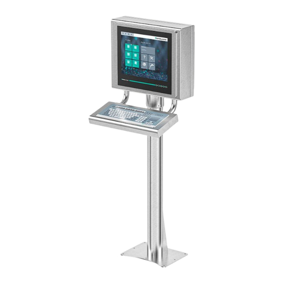
- Page 8 VisuNet GXP Product Description VisuNet GXP Pedestal Mounted with Keyboard/Mouse Figure 2.2 VisuNet GXP system mounted in AG1 Housing with Pedestal5 -1458-* and EXTA2 keyboard/mouse (ordered separately) Note For a description of the product model nomenclature, see the VisuNet GXP PC or VisuNet GXP RM product datasheets at www.pepperl-fuchs.com.
-
Page 9: Technical Specifications
VisuNet GXP Product Description Technical Specifications Technical Data RM-GXP* Hardware Processor Intel® Atom™ Bay Trail E3827 1.75 GHz 2048 MB DDR3L Mass storage 32 GByte industrial grade MLC SSD Software Operating system VisuNet RM Shell 5.x (based on Microsoft® Windows® 10 IoT LTSB) Technical Data PC-GXP* Hardware Processor... - Page 10 1 x fiber optic 1000BASE-SX (Multimode) or 1 x fiber optic 1000BASE-LX (Singlemode) 1 x USB 2.0 (Ex e) 2 x USB 1.1 (Ex i; intended for Pepperl+Fuchs keyboard and mouse) 1 x DC or AC power in (via power supply unit)
- Page 11 VisuNet GXP Product Description Mechanical specifications Degree of protection IP66 (individual components and entire sys- tem with housing) Material Internal: Panel: anodized aluminum (TCU, PSU), pow- der coated aluminum (DPU) External: Bezel: stainless steel AISI 304 (1.4301) System housing: stainless steel AISI 304 (1.4301), ground smooth, typical surface roughness Ra = 0.8 µm Mass...
-
Page 12: Dimensions
VisuNet GXP Product Description Dimensions Dimensions with AG1 Housing and Pedestal Figure 2.3 Dimensions with StandardLine Pedestal5-1458-Fix and EXTA2 keyboard/mouse—sample configuration Note Keyboard/mouse and pedestal are ordered separately. - Page 13 VisuNet GXP Product Description Panel Dimensions with Bezel Panel Cut-Out Dimensions Cut-out dimensions: 480 x 400 mm. For more information, see chapter 3.5.
-
Page 14: Disposal
VisuNet GXP Product Description Wall Mount Dimensions Figure 2.4 Wall mount dimensions with additional wall brackets (#198768) Disposal Follow all local and any other requirements for disposing of electronic equipment. When dis- posing of any system component, mark VOID across all certification labels. -
Page 15: Mechanical Installation
VisuNet GXP Mechanical Installation Mechanical Installation General Installation Requirements Observe the following requirements when installing the system components. • The equipment must be installed by competent personnel in accordance with the instruc- tions. National laws and regulations must be observed. •... -
Page 16: System Installation
VisuNet GXP Mechanical Installation System Installation 3.3.1 Preparation for System Installation Warning! Proper installation on the floor It is the installer's responsibility to select a suitable location with sufficient strength to hold the equipment. It is the installer's responsibility to select the proper screws based on the installa- tion conditions. -
Page 17: Preparing The Gxp Panel/Housing
VisuNet GXP Mechanical Installation StandardLine Pedestal Floor-Mount Hole Pattern BasicLine Pedestal Floor-Mount Hole Pattern 3.3.2 Preparing the GXP Panel/Housing The VisuNet GXP comes pre-assembled and consists of the core components display unit, power supply unit, and thin client unit / power supply unit. If the AG1 housing option is chosen, the panel is pre-mounted in the housing. - Page 18 NEVER use a display unit with a scratched front screen in a hazardous area. If the surface is damaged in any way, return the display unit to Pepperl+Fuchs at once and replace it with a new one. Preparing the Housing Remove the box and leave the protective foam blocks on the housing.
- Page 19 VisuNet GXP Mechanical Installation Remove and discard the screws from the bottom of the housing.
-
Page 20: Preparing The Standardline Pedestal
VisuNet GXP Mechanical Installation 3.3.3 Preparing the StandardLine Pedestal A variety of pedestals are available for floor mounting. For a complete list of available mounting options, see the mounting options datasheet. Pedestals are shipped with an attached protec- tive earth (PE) wire and screws for mounting the VisuNet GXP AG1 housing to the pedestal: 6 x M8 countersunk screws and 2 x M6 countersunk screws. - Page 21 VisuNet GXP Mechanical Installation Bottom of Pedestal PE stud M25 opening M20 opening M20 plug Warning! Connection to the PE stud Connection to the PE stud is mandatory. Opening Size Wrench Size Cable Diameter Torque 24 mm 7 ... 13 mm 12 Nm 29 mm 9 ...
- Page 22 VisuNet GXP Mechanical Installation Attach the cable to the pull wire.
- Page 23 VisuNet GXP Mechanical Installation Pull the cable through the cable entry and out the top of the pedestal. Pull the cable through the pedestal so that 50 cm of cable is hanging out of the top of the pedestal. Repeat the preceding steps for each cable that must be routed through the pedestal.
-
Page 24: Attaching The Pedestal To The Housing
VisuNet GXP Mechanical Installation 3.3.4 Attaching the Pedestal to the Housing Warning! Risk of injury Lifting the GXP housing on your own may cause injury. Do not attempt to lift the device on your own. Use a crane or have another person help you. Mounting the Pedestal Rest the pedestal on the box that the GXP housing was shipped in. - Page 25 VisuNet GXP Mechanical Installation Tighten the 6 x M8 screws in a criss-cross pattern to 20 Nm. Tighten the 2 x M6 screws to 12 Nm.
- Page 26 VisuNet GXP Mechanical Installation Positioning and Floor-Mounting the GXP Remove the box from under the pedestal and carefully position the system upright on the floor with a crane or the help of another person. Mount the pedestal onto the floor using suitable screws. Warning! Proper floor mounting It is the installer's responsibility to select a suitable location with sufficient...
-
Page 27: Opening The Housing
VisuNet GXP Mechanical Installation 3.3.5 Opening the Housing The GXP housing is hinged and opens to the left. Opening the GXP Warning! Risk of Damage and Injury Opening the GXP housing before the pedestal is mounted onto the floor may cause the housing and pedestal to tip over. - Page 28 VisuNet GXP Mechanical Installation Pull the right side of the housing front away from the back part of the housing.
-
Page 29: Grounding The Housing To The Pedestal
VisuNet GXP Mechanical Installation 3.3.6 Grounding the Housing to the Pedestal Warning! Customer responsibility to verify grounding path Check the grounding path after completing system installation. The AG1 housing comes with a pre-installed PE wire that is connected from the inside-top of the housing to the inside-back of the housing. - Page 30 VisuNet GXP Mechanical Installation Replace the nuts and washers. Fasten the nuts and washers with a torque of 7.5 Nm. Figure 3.2 Grounding Concept Housing PE stud (hexagon socket) Contact washer Cable lug Flat washer Spring washer...
-
Page 31: Mounting The Keyboard
VisuNet GXP Mechanical Installation 3.3.7 Mounting the Keyboard Remove the plug and screws from the bottom of the housing To remove the plug, open the housing (see see chapter 3.3.5). Hold the the inside nut while removing the plug from the outside with a flat-head screwdriver. - Page 32 VisuNet GXP Mechanical Installation Pull the keyboard wire through the plug and tighten the screws to 4.5 Nm. Note The keyboard is an intrinsically safe device. Refer to the control drawings and relevant installation requirements. For proper electrical termination of the keyboard, refer to the TCU/PCU and EXTA2 keyboard manuals.
-
Page 33: Mounting The Scanner Holder To The Ag1 Housing
VisuNet GXP Mechanical Installation 3.3.8 Mounting the Scanner Holder to the AG1 Housing Required Installation Tools • Size 3 hex wrench • Safety gloves All tools should be torque controlled if a torque is specified. Figure 3.3 #548268 scanner holder compatible with AG1 housing... - Page 34 VisuNet GXP Mechanical Installation Mounting the Scanner Holder Open the AG1 housing. See chapter 3.3.5 Remove the screws on the right side of the AG1 housing. Affix the barcode reader using the screw included in delivery with the barcode reader holder. Use a hex key to put the first screw (with lock washer and sealing washer) through the drilled hole on the right side of the AG1 housing.
- Page 35 VisuNet GXP Mechanical Installation Follow the same steps to mount the holder bracket-AG1-IDMx61-B-N0 for the IDM base station (#548395) to the AG1 housing.
- Page 36 VisuNet GXP Mechanical Installation Figure 3.4 Technical drawing - dimensions with scanner holder.
-
Page 37: Installing The Handheld 1-D/2-D Code Reader
VisuNet GXP Mechanical Installation Figure 3.5 Dimension drawing with holder bracket 3.3.9 Installing the Handheld 1-D/2-D Code Reader Required Components • S3 or S4 Interface (thin client / PC-unit) • DATL-IDM-DB-S-XX00-N0 • CBL-IDMx60-D-J1-S-S18-N0 or CBL-IDMx60-D-J1-S-C38-N0 • IDM-Z1-160-D-1D-J1-*, IDM-160-D-1D-J1-*, IDM-Z1-260-D-2D-J1-S1-N-N0, or IDM-Z1- x61-*, IDM-x61-* in combination with required Bluetooth handheld barcode reader •... - Page 38 VisuNet GXP Mechanical Installation Required Installation Tools • Flat head screwdriver • 19 mm socket wrench for counter nut and connector • Size 2.5 hex wrench for cable tie screws • Safety gloves All tools should be torque controlled if a torque is specified. Connector cable DATL-IDM-DB-S-XX00-N0 Figure 3.6 Connector cable for wired 1-D scanner IDM-Z1-160-D-1D-J1- S-* (S3-Interface required)
- Page 39 VisuNet GXP Mechanical Installation Installing the cable DATL-IDM-DB-S-XX00-N0 Open the AG1 housing. See chapter 3.3.5 Remove the plug at the bottom-right side of the housing by holding the screw steady from below with a screwdriver while loosening the screw from above with a wrench.
- Page 40 VisuNet GXP Mechanical Installation Guide the open wire end of the cable DATL-IDM-DB-S-XX00-N0 through the hole. Place the M16 counter nut over the end of the cable.
- Page 41 VisuNet GXP Mechanical Installation Pull the socket into the housing and tighten it with the M16 counter nut. Tighten the nut with a torque of 5 Nm. Protect the cable from mechanical damage by fastening it with a cable tie.
- Page 42 VisuNet GXP Mechanical Installation Route the cable through the cable gland on the TCU/PCU. Install the wire ends per the tables below. Wiring Guide DATL-IDM-DB-S-XX00-N0 to IDM-Z1-160* and Base Station IDM-Z1-x61-B-N0* Ex i Cable Terminal Signal Name Direction Assignment Color coding Pin M12 con- nector Xx.1...
-
Page 43: Replacing A Visunet Ex1 With The 19-Inch Visunet Gxp
VisuNet GXP Mechanical Installation Connecting the IDM* Barcode Reader Connect the plug (M12 male connector) of the barcode reader to the socket and tighten it firmly. Coded Plug and Socket Figure 3.7 The plug and socket are coded. Match the coding on the plug and socket before tightening. Replacing a VisuNet EX1 with the 19-Inch VisuNet GXP General Requirements •... -
Page 44: Removing Visunet Ex1 From Ag1 Housing
VisuNet GXP Mechanical Installation 3.4.1 Removing VisuNet EX1 from AG1 Housing Required Installation Tools • 3-mm wide flat head screwdriver • Phillips head screwdriver • Cable gland installation tool • Ratchet strap or, preferably, a second person to help you •... - Page 45 VisuNet GXP Mechanical Installation Remove the VisuNet EX1 from the AG1 housing. Be sure to wear safety gloves to protect your hands. Warning! Risk of damage When setting the VisuNet EX1 down, do not rest the EX1 on the edge of the front plate.
-
Page 46: Installing Visunet Gxp Into Ag1 Housing
VisuNet GXP Mechanical Installation 3.4.2 Installing VisuNet GXP into AG1 Housing Required Components • VisuNet GXP 19-inch prepared for panel mounting (S2 option) • AG1 housing Required Installation Tools • 3-mm wide slot head screwdriver • Phillips head screwdriver • Cable gland installation tool •... - Page 47 VisuNet GXP Mechanical Installation Installing the VisuNet GXP Connect the AG1 housing to an external equipotential bonding conductor. Close the AG1 housing, but do not yet insert the screws to fasten the housing closed. Insert the 19-inch VisuNet GXP into the opening of the AG1 housing. Be sure to wear safety gloves to protect your hands.
- Page 48 VisuNet GXP Mechanical Installation Wire the terminal compartments as described in the VisuNet TCU/PCU manual. Terminal Compartment Ex e Terminal Compartment Ex i Terminal Compartment for optional modules Fiber Optic TX+/D1+ TX RX TX-/D1- RX+/D2+ RX-/D2- Figure 3.8 Terminal compartments Close the covers of the terminal compartments and ensure that they are tightly sealed in accordance with regulations Close the AG1 housing.
-
Page 49: Panel Mount Installation
VisuNet GXP Mechanical Installation Panel Mount Installation Warning! Proper installation It is the installer's responsibility to select a suitable location with sufficient strength to hold the equipment. It is the installer's responsibility to select the proper screws based on the installa- tion conditions. - Page 50 VisuNet GXP Mechanical Installation Note If installing the device in a different housing, ensure that the operating temperature is within the specified range or up to +50 °C. The panel mount option is mounted from the front and placed outside the wall surface. The monitor protrudes slightly and is exposed.
- Page 51 The cutout dimensions and stud location must match those on the GXP exactly. Figure 3.10 VisuNet GXP flush mounted Note For more options and accessories, contact your local Pepperl+Fuchs sales representative.
-
Page 52: Wall Mount Installation
VisuNet GXP Mechanical Installation Wall Mount Installation Warning! Proper installation It is the installer's responsibility to select a suitable location with sufficient strength to hold the equipment. It is the installer's responsibility to select the proper screws based on the installa- tion conditions. - Page 53 VisuNet GXP Mechanical Installation Installation Steps Open the AG1 housing. See chapter 3.3.5 Install cable glands with counter nuts and the two ground studs into the AG1 back wall where indicated in the image below. Close the AG1 housing. Install the wall bracket to the AG1 housing with the included M8 screws and lock washers. Install the assembled unit to the wall with the appropriate mounting material.
-
Page 54: Appendix
*, IDM-x61-* base station to AG1 housing Material: stainless steel AISI 304 (1.4301) Assembly: right side of AG1 housing Includes bracket and installa- tion materials Note: base station and cables not included! Note For more options and accessories, contact your local Pepperl+Fuchs sales representative. -
Page 55: Ul Control Drawing
VisuNet GXP Appendix UL Control Drawing Connections Hazardous Location Hazardous Location Class I, Division 2, Groups A, B, C, D; T4 Class I, Division 2, Groups A, B, C, D; T4 Class II, Division 2, Groups F, G; T4 Class II, Division 2, Groups F, G; T4 Class III Class III Class I Zone 2, Group IIC;... - Page 56 Pepperl+Fuchs Quality Download our latest policy here: www.pepperl-fuchs.com/quality www.pepperl-fuchs.com © Pepperl+Fuchs · Subject to modifications Printed in Germany / DOCT-5945C...
Need help?
Do you have a question about the VisuNet GXP Series and is the answer not in the manual?
Questions and answers