
Related Manuals for Vision Engraving & Routing Systems 5 Series


Summary of Contents for Vision Engraving & Routing Systems 5 Series
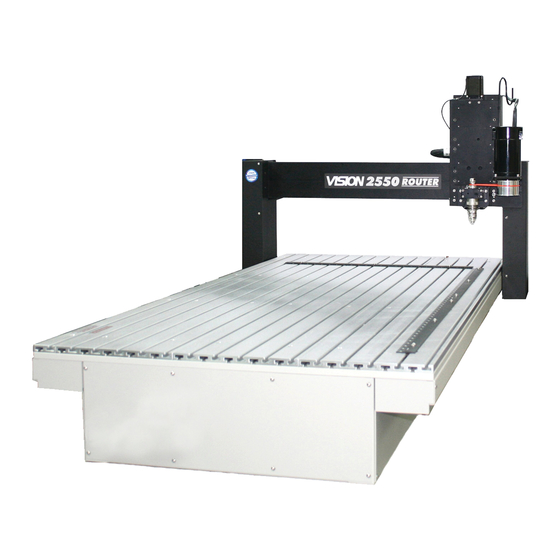
- Page 1 Vision 1624R, 2525 and 2550 Series 5 User Guide © 2019 Vision Engraving Systems Revised: 7/3/2019...
- Page 2 Vision 1624R, 2525 and 2550 Series 5 Installation Guide © 2019 Vision Engraving Systems All rights reserved. No parts of this work may be reproduced in any form or by any means - graphic, electronic, or mechanical, including photocopying, recording, taping, or information storage and retrieval systems - without the written permission of the publisher.
-
Page 3: Table Of Contents
Contents Table of Contents Part I Introduction 1 Disclaimer and Warranty Information ........................... 5 2 Safety Precautions ........................... 7 3 Computer Requirements ........................... 10 4 Vision software security device ........................... 10 5 General Electrical and Facility Requirements ........................... 11 Part II 1624R, 2525 and 2550 Series 5 Installation 1 Locating the Router ........................... - Page 4 Vision Series 5 Controller User Manual Search screen ................................109 Origin Select screen ................................112 Surface Location screen ................................116 Utilities screen ................................117 Diagnostic screen ................................118 3 Set Surface Procedures ........................... 118 4 Set Home Procedure ........................... 121 Part VII Sending Jobs to Your Machine Part VIII Controller Maintenance Part IX Using the Measure Feature...
-
Page 5: Part I Introduction
Introduction Introduction About This Manual This manual is designed to provide you with information about your Vision Series 5 Controller, Engraver or Router. Beginning with unpacking the machine and continuing through installation, operation and maintenance, this manual does not attempt to teach the user how to become an expert in engraving, computer usage, or engraving software usage. - Page 6 Vision Series 5 Controller User Manual The warranties for Third-Party Hardware and Third-Party Software shall run directly from the manufacturers of such hardware and software to the user. Vision makes no warranties, expressed or implied, with regard to Third-Party Hardware or Third-Party Software. Vision does not warrant any product, component, or part not manufactured by Vision that was not supplied by Vision.
-
Page 7: Safety Precautions
Introduction Safety Precautions Ø WARNING: Do not attempt to operate this equipment until you have read thoroughly and understood completely the instructions contained in this User's Guide! Failure to comply may result in damage to the equipment and/or inflict serious personal injury! Ø... - Page 8 Vision Series 5 Controller User Manual Ø Before any servicing, disconnect the power cord. Ø To avoid electric shock or equipment damage, connect the power to this machine according to the suggestions in this guide and in compliance with all applicable regulations. Make sure the machine is properly grounded.
- Page 9 Introduction Ø Make sure workpiece is properly fastened to table before starting job. Ø Turn on vacuum table or make sure clamps and other fixtures are tightly fastened. If workpiece moves during operation you can damage the machine, the workpiece, and serious personal injury may occur to the operator.
-
Page 10: Computer Requirements
Vision Series 5 Controller User Manual Computer Requirements Minimum System Requirements: CPU: Intel i5 2.6-3.0GHz Hard Drive: 256 GB free space RAM: 8 GB Operating System: Windows 10 (32/64 bit) Windows 8 (32/64 bit) Windows 7 (32/64 bit) NOTE: Windows updates must ALL be installed Ports: 1 USB port for security dongle 1 USB port for Ethernet adapter to connect machine... -
Page 11: General Electrical And Facility Requirements
Introduction General Electrical and Facility Requirements Machine Model Requirements 1624R, 2525, 2550 Router with T-Slot Table With Engraving Head One 110 VAC 15 Amp OR One 220 VAC 10 Amp Single Phase With High Frequency Router Head One 110 VAC 15 Amp OR One 220 VAC 10 Amp Single Phase (Vision controller) AND One 220 VAC 30 Amp Single Phase (3 HP router) 2550 Router with Vacuum Table... -
Page 12: Part Ii 1624R, 2525 And 2550 Series 5 Installation
Vision Series 5 Controller User Manual 1624R, 2525 and 2550 Series 5 Installation Locating the Router Locate all equipment indoors on a flat surface and on a solid foundation. Temperature must remain between 40°F and 85°F. Do not expose machine to direct sunlight, rain, vibration, dampness, or explosive environments. The machine dimensions are: 1624R - 44"... - Page 13 1624R, 2525 and 2550 Series 5 Installation If ordered, the UNIST Misting System requires a compressed air supply regulated to no more than 60 psi. © 2019 Vision Engraving Systems...
-
Page 14: Installation Layout Diagrams
Vision Series 5 Controller User Manual Installation Layout Diagrams 2.2.1 2525 and 2550 Layout Diagrams Vision 2525 installation layout © 2019 Vision Engraving Systems... - Page 15 1624R, 2525 and 2550 Series 5 Installation Vision 2550 installation layout © 2019 Vision Engraving Systems...
- Page 16 Vision Series 5 Controller User Manual Vision 2550 vacuum table installation layout © 2019 Vision Engraving Systems...
-
Page 17: 1624R Router Layout Diagram
1624R, 2525 and 2550 Series 5 Installation 2.2.2 1624R Router Layout Diagram 1624R Table Descriptions (Refer to the diagrams on the following pages) Table Base Plate. This is the large flat plate upon which everything else is mounted. All mechanical alignments are referenced to this plate, so the space upon which you place the engraving table must be a reasonably level surface. - Page 18 Vision Series 5 Controller User Manual Y-Axis Linear Rails. Mounted on the table base plate are stainless steel rails with sealed bearings, which control the motion of the T-Slot table in the Y-axis. T-Slot Table. The T-Slot table is an aluminum bed which allows placement of the engraving material or special clamps and fixtures.
- Page 19 1624R, 2525 and 2550 Series 5 Installation Spindle Cable. Connects to the machine's controller and provides power to the engraving or router motor. Auxiliary Power Cable. This cable is pre-wired on all 16 and 25 Series Router models. It connects an alternate power supply to the High Frequency Router Motor or Porter Cable Router Motor.
- Page 20 Vision Series 5 Controller User Manual 1624R Diagrams © 2019 Vision Engraving Systems...
- Page 21 1624R, 2525 and 2550 Series 5 Installation © 2019 Vision Engraving Systems...
- Page 22 Vision Series 5 Controller User Manual © 2019 Vision Engraving Systems...
-
Page 23: 2525/2550 Table Descriptions
1624R, 2525 and 2550 Series 5 Installation 2525/2550 Table Descriptions (Refer to the diagrams on the following pages) Table Base Plate. This is the large flat plate upon which everything else is mounted. All mechanical alignments are referenced to this plate, so the space upon which you place the engraving table must be a reasonably level surface. - Page 24 Vision Series 5 Controller User Manual Router Motor. The router motor is mounted on the front of the carriage assembly. The router motor turns the cutter during the routing process. Several motors and spindles are available for specialized purposes and are described in other sections of this manual. 25 Pin Connector.
- Page 25 1624R, 2525 and 2550 Series 5 Installation Misting System Port. Located on the rear of the carriage assembly, this port is used to connect the power cable to the optional UNIST Misting System. DACS Power Port. Located on the rear of the carriage assembly, this port is used to connect to the power cable supplying the optional Ethernet DACS Camera.
- Page 26 Vision Series 5 Controller User Manual 2525/2550 Diagrams © 2019 Vision Engraving Systems...
- Page 27 1624R, 2525 and 2550 Series 5 Installation © 2019 Vision Engraving Systems...
-
Page 28: 2550 Vacuum Table
Vision Series 5 Controller User Manual 2550 Vacuum Table The optional vacuum table for the 2550 is split into 2 vacuum zones for the left and right sides of the table. Each side has a valve to control the vacuum applied to it. Vacuum from the supplied vacuum pump is connected to the vacuum tube (not shown) under the machine's base. - Page 29 1624R, 2525 and 2550 Series 5 Installation Vacuum Table Top View © 2019 Vision Engraving Systems...
- Page 30 Vision Series 5 Controller User Manual Vacuum Valve Diagram The valves controlling the vacuum to the table are mounted on a plate attached to the machine's stand. © 2019 Vision Engraving Systems...
-
Page 31: 2550 Vacuum Pump Connection - Vacuum Table Model Only
1624R, 2525 and 2550 Series 5 Installation 2550 Vacuum Pump Connection - Vacuum Table Model Only The Main Vacuum Port on the 2550 Router is located on the bottom of the valve panel as shown below. The user will need to attach the valve panel to the end of the table as shown in the photo and connect the flexible hose from the vacuum inlet on the filter canister to the Main Vacuum Port on the valve panel. - Page 32 Vision Series 5 Controller User Manual The vacuum pump has been supplied with an electrical connector designed for a 20 amp, 220 VAC, single phase power supply. A qualified and licensed electrician must be used to complete all wiring and grounding of the vacuum pump according to all state, local, and national electrical codes.
-
Page 33: Series 5 Controller Connections
1624R, 2525 and 2550 Series 5 Installation Series 5 Controller Connections On the rear of the Vision Series 5 controller, there are 13 connection ports. Plug in all of the cables unless noted below. 1. The Aux Table plug connects to a 15 pin connector on the Vision 2525 and 2550. NOTE: This is not used with the 1624R. - Page 34 Vision Series 5 Controller User Manual Vision Series 5 controller (rear view) © 2019 Vision Engraving Systems...
- Page 35 1624R, 2525 and 2550 Series 5 Installation Vision Series 5 pendant (rear view) NOTE: If the emergency stop screen appears on the LCD when the machine is powered on, then the emergency stop button is pressed in. This can either be the emergency stop button on the table or the emergency stop button on the pendant.
-
Page 36: Pendant Holder Installation
Vision Series 5 Controller User Manual Pendant Holder Installation The 2525 and 2550 machines are shipped with a Pendant Holder to give the user a place to secure the Pendant. NOTE: Not required for 1624R. To install the Pendant Holder on the 25 Series machines, follow the below procedure. ©... - Page 37 1624R, 2525 and 2550 Series 5 Installation © 2019 Vision Engraving Systems...
-
Page 38: Spindle Options
Vision Series 5 Controller User Manual Spindle Options 2.9.1 Engraving Head The Motor Plug connects to the Spindle Port and the Proximity Sensor Plug connects to the Proximity Sensor Port on the back of the Carriage. Carriage - rear view ©... - Page 39 1624R, 2525 and 2550 Series 5 Installation Engraving Head Diagram - Installed © 2019 Vision Engraving Systems...
- Page 40 Vision Series 5 Controller User Manual Engraving Head Removal Procedure 1. Remove the Motor Plug from the back of the Carriage and place it over the Cable/Hose Hanger. 2. Loosen the four mounting screws and remove. The Engraving Head will be held in place on the Rail Plate by the two Dowel Pins on the back of the Mounting Plate.
-
Page 41: High Frequency Router Head
1624R, 2525 and 2550 Series 5 Installation 2.9.2 High Frequency Router Head Wiring Connections for Inverter (used with High Frequency Router Head only) NOTE: The Auxiliary Power Cable is pre-wired on all 16 and 25 Series Routers. Remove Inverter Cover and feed the Auxiliary Power Cable through hole in bottom of Inverter. Connect the three black wires labeled, T1, T2 and T3, to their respective connection points. - Page 42 Vision Series 5 Controller User Manual connect the MOD/BUS Cable to the machine controller's MOD/BUS port. © 2019 Vision Engraving Systems...
- Page 43 1624R, 2525 and 2550 Series 5 Installation Carriage Wiring Connections The Motor Plug connects to the Spindle Port on the back of the Carriage. Carriage (rear view) © 2019 Vision Engraving Systems...
- Page 44 Vision Series 5 Controller User Manual Mounting the Inverter on the 25 Series Table Stand The Inverter is mounted on the top-left corner of the machine's stand. There are two flanges mounted on the rear of the inverter. These flanges are placed in the inside of the stand's legs. Screws are included with the inverter to secure the inverter to the stand.
- Page 45 1624R, 2525 and 2550 Series 5 Installation High Frequency Router Head Diagram - Installed © 2019 Vision Engraving Systems...
- Page 46 Vision Series 5 Controller User Manual High Frequency Router Head Removal Procedure 1. Remove the Motor Plug from the back of the Carriage and place the plug over the Cable/Hose Hanger. 2. Loosen the two thumbscrews holding the Router Vacuum Head in place. 3.
-
Page 47: Nsk 50,000 Rpm Spindle
1624R, 2525 and 2550 Series 5 Installation High Frequency Router Head Removal - continued 4. Loosen the four mounting screws and remove. The Router Head will be held in place on the Rail Plate by the two Dowel Pins on the back of the Mounting Plate. 5. - Page 48 Vision Series 5 Controller User Manual Electrical Connections If the machine was ordered with the NSK Spindle option, an Analog Spindle port was installed on the machine's controller. Connect the Analog Spindle Cable to this port on the controller and the other end to the Analog Spindle Port on the NSK Power Supply Unit (The Analog Spindle Cable is identical to the Table Cable used to connect the controller to the engraver or router's table.
- Page 49 1624R, 2525 and 2550 Series 5 Installation Installing Cutting Tools The NSK Spindle can accept either 1/8" or 1/4" cutting tools., depending on which collet was shipped with the system. The spindle will accept standard 2" shank bottom loading cutting tools. The collar at the bottom of spindle and the spindle shaft both have flat areas (tool slots) to allow the user to loosen or tighten the collet.
-
Page 50: High Speed Engraving Spindle
Vision Series 5 Controller User Manual 2.9.4 High Speed Engraving Spindle The High Speed Engraving Spindle is installed with the High Frequency Router Motor. It allows up to a 30,000 RPM spindle speed. Connections to the machine's Controller are the same as when only using the High Frequency Router Motor. - Page 51 1624R, 2525 and 2550 Series 5 Installation Dowel Pin Holes. 4. Install and tighten the 4 Mounting Screws. 5. Connect the Proximity Sensor Plug into the Proximity Sensor Port on the rear of the router Carriage. © 2019 Vision Engraving Systems...
- Page 52 Vision Series 5 Controller User Manual Router Rail Plate Carriage (rear view) © 2019 Vision Engraving Systems...
- Page 53 1624R, 2525 and 2550 Series 5 Installation High Speed Engraving Spindle - Mounted 6. Install the Drive Belt on to the Drive Pulley, then lightly stretch it of the top of the Spindle Pulley. NOTE: Do not excessively stretch the drive belt. The belt can be damaged by over-stretching and may slip and not drive the spindle properly.
- Page 54 Vision Series 5 Controller User Manual © 2019 Vision Engraving Systems...
- Page 55 1624R, 2525 and 2550 Series 5 Installation High Speed Spindle - Standard Spindle Differences The High Speed Spindle can be identified by looking at the spindle pulley (the driven pulley) on top of the spindle. The high speed spindle uses a much smaller diameter pulley than the standard engraving spindle (0.75"...
-
Page 56: Oscillating Knife
Vision Series 5 Controller User Manual 2.9.5 Oscillating Knife Place the Oscillating Knife Assembly against the face of the Router Rail Plate and align it to the Mounting Plate with the Alignment Pins. Secure the Assembly with 4 Mounting Screws as shown. ©... - Page 57 1624R, 2525 and 2550 Series 5 Installation Carriage Wiring Connections Connect the Oscillating Knife Cable to the rear of the carriage as shown. The other end of the cable connects to the top of the Oscillating Knife Assembly as shown. ©...
- Page 58 Vision Series 5 Controller User Manual © 2019 Vision Engraving Systems...
-
Page 59: Unist Misting System
1624R, 2525 and 2550 Series 5 Installation 2.9.6 UNIST Misting System The optional UNIST Misting System is designed to provide lubrication to the cutting tool and material when processing metals. The diagram shown below lists the main components and connections. This system requires a compressed air supply (60 PSI Max) to be connected to the inlet air line. - Page 60 Vision Series 5 Controller User Manual Additionally, the Misting System Power Plug on the router connects to the controller's Pump/Mist port with the supplied cable. © 2019 Vision Engraving Systems...
-
Page 61: Part Iii Network Connection
Network Connection Network Connection NOTE - This following section is shown on a Windows 10 PC. For Windows 7 or Windows 8, the screens are slightly different. Plug the USB end of the USB to Ethernet adapter into any open USB port on the computer. Right click on the Windows network icon in the lower right corner of the Windows screen. - Page 62 Vision Series 5 Controller User Manual Select "Change adapter options". Right click on the Asix USB Ethernet connection. Select Properties. © 2019 Vision Engraving Systems...
- Page 63 Network Connection Select "Internet Protocol Version 4 (TCP/IPv4). Select Properties. © 2019 Vision Engraving Systems...
- Page 64 Vision Series 5 Controller User Manual The screen below will appear. Enter the settings below. Select: Use the following IP address: Enter an IP address of: 192.168.100.100 Enter a Subnet mask of: 255.255.255.0 © 2019 Vision Engraving Systems...
- Page 65 Network Connection Select OK. Plug one end of the network cable into the USB to Ethernet adaptor. Plug the other end of the network cable into the COMPUTER connection in the back of the Vision Series 5 controller. The network connection is now complete. Please continue to the network setup section. ©...
-
Page 66: Part Iv Vision Mov Ui Software Installation
Vision Series 5 Controller User Manual Vision Mov UI Software Installation Power the Vision Series 5 controller on with the switch on the front. Insert the Vision USB dongle into the USB port on the computer. Navigate to the USB dongle in Windows File Explorer. - Page 67 Vision Mov UI Software Installation Select Step 1 Setup Machine. © 2019 Vision Engraving Systems...
- Page 68 Vision Series 5 Controller User Manual Select Next on the "Prerequisites Setup Wizard" screen. NOTE: This screen will not appear if the Windows feature is already installed on the computer. Select Next on the "Prerequisites" installation screen. NOTE: This screen will not appear if the Windows feature is already installed on the computer. ©...
- Page 69 Vision Mov UI Software Installation Select Next on the "Microsoft Vision C++ installation" screen. NOTE: This screen will not appear if the Windows feature is already installed on the computer. Select the I have read and accept the license terms box then select Install. NOTE: This screen will not appear if the Windows feature is already installed on the computer.
- Page 70 Vision Series 5 Controller User Manual Select Finish on the "Setup Complete" screen. NOTE: This screen will not appear if the Windows feature is already installed on the computer. Select Next on the "Welcome screen". © 2019 Vision Engraving Systems...
- Page 71 Vision Mov UI Software Installation Select Next on the "Choose a file location" screen. Select Install on the "Begin installation" screen. © 2019 Vision Engraving Systems...
- Page 72 Vision Series 5 Controller User Manual Select Close on the "Successful Install" screen. The VisMovUI screen will appear. Select the Machine in the "Machines Discovered on Network" screen and click Select. © 2019 Vision Engraving Systems...
- Page 73 Vision Mov UI Software Installation The VisMovUI program will appear. Select the Minimize button. The Vision Move UI program is now installed. Please continue to the network setup section. © 2019 Vision Engraving Systems...
-
Page 74: Part V Vision Software Installation
Vision Series 5 Controller User Manual Vision Software Installation Insert the Vision USB dongle into the USB port on the computer. Navigate to the USB dongle in Windows File Explorer. Select the Start or Start.exe file to begin. Select 1612 and larger. ©... - Page 75 Vision Software Installation Select Step 2 Install Vision Software. Select Next on the "Welcome" screen. © 2019 Vision Engraving Systems...
- Page 76 Vision Series 5 Controller User Manual Select Install on the "Ready to Install" screen. Select Finish on the "Complete Install" screen. © 2019 Vision Engraving Systems...
- Page 77 Vision Software Installation Select the language desired and select OK on the "Vision Pro install" screen. Make sure the USB dongle is installed and select Next on the "USB Flash Dongle" screen. © 2019 Vision Engraving Systems...
- Page 78 Vision Series 5 Controller User Manual Select Next on the "Vision 10 setup" screen. NOTE: The installation will display "Vision Pro 10 Setup", "Vision Expert 10 Setup" or "Vision Express 10 Setup" depending on which version has been purchased. Select the I accept the terms of the license agreement box then select Next on the "License Agreement"...
- Page 79 Vision Software Installation Select Next from the "Choose Destination Location" screen. NOTE: The installation folder will be either "C:\Vision Pro 10", "C:\Vision Expert 10" or "C:\Vision Express 10" depending on which version has been purchased. Select Next on the "Program Folder" screen. ©...
- Page 80 Vision Series 5 Controller User Manual The installation will continue. Select Vision S5 - Routers and select Next. Select the driver for the that matches the machine purchased and select Next. NOTE: If ADA drivers or a center origin driver is needed, select them also. ©...
- Page 81 Vision Software Installation Select Continue on the "Font Installation" screen. © 2019 Vision Engraving Systems...
- Page 82 Vision Series 5 Controller User Manual The installation will search for Vision fonts. Select the disk drive to search for additional fonts that may be on the computer and select Yes. NOTE: Typically drive C:\ is selected. © 2019 Vision Engraving Systems...
- Page 83 Vision Software Installation The installation will search for additional fonts. NOTE: This may take a few minutes. Select OK on the "Font Installation Complete" screen. © 2019 Vision Engraving Systems...
- Page 84 Vision Series 5 Controller User Manual Select Finish to complete the installation. NOTE: The install may or may not ask to restart the computer. Select Exit from the initial screen. The Vision 10 software and Vision Manuals icon will now be on the Windows desktop. ©...
-
Page 85: Part Vi Operation
Vision Software Installation Operation Starting the Vision Mov UI spooler The Vision Mov UI spooler program must be running and connected before proceeding. The Vision Mov UI program should start automatically after the program is installed and when the computer is restarted. The screen below will appear when it is running. If it is not running, select the Vision Mov UI icon from the Windows desktop. - Page 86 Vision Series 5 Controller User Manual The VisMovUI program will appear. Select the Minimize button. The Vision Move UI program will now be displayed in the Windows task bar on the right side. It will either be displayed to the right of the up arrow or it will be displayed when the up arrow is selected. IMPORTANT: Only one Vision Mov UI spooler can be running per machine at a time.
-
Page 87: Pendant Controls
Operation Pendant Controls The Pendant controls all of the movement of your Vision engraver or router. Below is a picture of the Pendant. The function of each item is explained below. © 2019 Vision Engraving Systems... -
Page 88: Startup Screen
Vision Series 5 Controller User Manual 6.2.1 Startup screen When the Vision controller is powered on and the Vision Move UI spooler is connected, the start up screen will appear. Select Start Homing and the machine will initialize and move to the home position. Pressing the Stop button will stop the machine from moving. -
Page 89: Emergency Stop Button
Operation 6.2.2 Emergency Stop Button This button will stop engraving, leaving the cutter in the down position and will power off the X, Y and Z stepper motors. It will also power off the spindle motor and auxiliaries such as a vacuum chip removal system or misting system. - Page 90 Vision Series 5 Controller User Manual Emergency Stop button released: Press Reset Safety Monitor after the emergency stop button has been released. The machine will now move to the home position. The job that was running can be restarted or skipped. NOTE: All emergency stop buttons on the table and pendant must be released for the machine clear the emergency stop message.
-
Page 91: Setup Screen
Operation 6.2.3 Setup screen The Setup screen is the main screen. All of the options start from this screen. The Setup, Run, Adjust and Search buttons will appear on most other screens allowing for quick access to them. Pressing Goto Origin moves the spindle to the currently set origin. Pressing Goto Home moves the spindle to the machine home location. - Page 92 Vision Series 5 Controller User Manual The job information screen will be displayed. Select the image button to display a graphical preview of the currently loaded job. Press the zoom in and out buttons as needed. © 2019 Vision Engraving Systems...
-
Page 93: Run Screen
Operation Pressing the zoom button will return to the standard view. The scroll bars can also be used as needed when the view is zoomed in. Select back two times to return to the setup screen. 6.2.4 Run screen The run screen will be displayed automatically when either a job is sent to the controller (while on the setup screen), a job is selected from the setup screen or the run button is pressed. - Page 94 Vision Series 5 Controller User Manual Pressing the start button will start running the job. While a job is running, the stop button will stop the machine immediately. When the stop button is pressed, the restart and continue buttons will appear. Pressing restart will re-run the job from the beginning.
- Page 95 Operation While a job is running, the elapsed time field and the % complete field will display how long the job has been running and the percentage that it is complete. The status field will display messages. The status area displays the following while the job is running: Spindle RPM: The rotation speed of the spindle.
- Page 96 Vision Series 5 Controller User Manual Using the goto first position feature is typically used to manually set the Z surface location at the start of the engraving location. The surface location can be set with the surface sensor or manually set. Both ways are described below.
- Page 97 Operation NOTE: Pressing Abort will stop the sense surface procedure. 6. Remove the clip from the spindle before starting the job. NOTE: This feature is used only with the surface sensor option. Manual surface setting: 1. Press the setup button 2.
-
Page 98: Set Xyz Screen
Vision Series 5 Controller User Manual The show outline button will use the red laser pointer to draw a box around the engraving area of the currently loaded job. Pressing stop while the outline is running will stop this process. NOTE: If a job is not currently loaded in the machine, the show outline button will be grayed out. - Page 99 Operation HINT: Pressing the jog speed button will toggle the jog speed between fast, medium and slow. As the jog buttons are pressed, the location of the spindle will be displayed. Both the relative and absolute coordinates are displayed. The absolute value is the distance from the machine origin to the current location of the spindle. The relative value is the distance from the currently selected origin to the current location of the spindle.
- Page 100 Vision Series 5 Controller User Manual The Set Origin button is used to set a user defined home location. To define an origin location, use the X & Y jog buttons to move the spindle to a point you want to set as the origin.
- Page 101 Operation The Set Surface button is used to set the material surface. This is only needed when the proximity sensor is not being used. The procedure for setting the surface is as follows: 1. Press the X & Y jog buttons to move the spindle over the material to be engraved. 2.
- Page 102 Vision Series 5 Controller User Manual 4. Use the jog buttons on the Set XYZ screen to move the tool over the location where the surface will be set. 5. Press the Sense button on the Sense Material section on the Set XYZ screen. Once the cutter touches the surface block as shown below, the spindle will stop moving down and the surface will be set.
- Page 103 Operation The spindle RPM and spindle button are used in conjunction with each other. They are used to manually start the currently selected spindle motor. Select the spindle RPM button. Enter the desired RPM value and press enter. The Spindle RPM value will be changed. Press the spindle button.
-
Page 104: Job Select Screen
Vision Series 5 Controller User Manual 6.2.6 Job Select screen The job select screen is used to manually load a job into the machine. Pressing the job select button on the setup screen will allow a job to be selected. Select the job to load in the job list and then press select. - Page 105 Operation When the job is loaded, the run screen will open automatically. Press start to run the job. If the job is no longer needed, the skip job button can be pressed. The unload job button can also be pressed from the job select screen. NOTE: The job is only unloaded from the machine.
- Page 106 Vision Series 5 Controller User Manual Select the job folder button. Select the desired folder location and select OK and then close. © 2019 Vision Engraving Systems...
-
Page 107: Adjust Screen
Operation 6.2.7 Adjust screen The adjust screen allows the XY speed, Z speed and spindle speed to be adjusted while the machine is running a job. © 2019 Vision Engraving Systems... - Page 108 Vision Series 5 Controller User Manual Pressing either the XY speed, Z speed or spindle speed will display a numeric keypad. Enter the desired speed increase or decrease percentage and press enter. The default value of 100 is the speed that was sent over in the job file from the material settings in the Vision software.
-
Page 109: Search Screen
Operation 6.2.8 Search screen The search screen will allow the job to be started or continued from any location in the job. This feature can be accessed when a job is loaded or if a job is stopped while running. When a job is loaded or stopped, press the search button. - Page 110 Vision Series 5 Controller User Manual HINT: Pressing the jog speed button will toggle the jog speed between fast, medium and slow. Pressing the shape button in snap to closest will move the tool to the closest object to where the tool was jogged to.
- Page 111 Operation NOTE: This is the line number of the output file, not the line number of the text being engraved. The status line displays information on the location of the tool. The X/Y values display the location of the tool. This will be displayed in inches, millimeters, feet or meters depending on how the machine is configured on the Utilities screen.
-
Page 112: Origin Select Screen
Vision Series 5 Controller User Manual 6.2.9 Origin Select screen The origin select screen is used to select the origin to be used. Pressing the origin select button on the setup screen will allow a different origin to be selected. Fourteen different preset home origins can be stored in the Vision Series 5 controller. - Page 113 Operation Select preset home origin location by pressing the "Active" button to the right of the desired number and press OK. To set the location for the selected preset home origin, press the Set XYZ button from the setup screen. Use the jog buttons to the spindle left &...
- Page 114 Vision Series 5 Controller User Manual Both the relative and absolute coordinates are displayed. The absolute value is the distance from the machine origin to the current location of the spindle. The relative value is the distance from the currently selected origin to the current location of the spindle. HINT: The laser pointer can be used in conjunction with the set origin button to set the origin at the pointer location instead of the spindle location.
- Page 115 Operation Press the Set Origin button to store the location into the preset home origin that was selected on the origin select screen. Going back into the preset home origin option will then display the X and Y position that was set. In the example below, a value of 2 inches on the X and 3 inches on the Y were set for preset home 2.
-
Page 116: 6.2.10 Surface Location Screen
Vision Series 5 Controller User Manual 6.2.10 Surface Location screen The surface location screen is used to select a flat or irregular shaped surface. Pressing the surface location select button on the setup screen will display the select material or surface map screen. -
Page 117: 6.2.11 Utilities Screen
Operation Press the Material option to use a flat surface or press Surface Map to use an irregular surface material. Press OK to return to the previous menu. If an irregular surface is being engraved, press the Surface Map button. 6.2.11 Utilities screen The Utilities screen is used to for several options. -
Page 118: 6.2.12 Diagnostic Screen
Vision Series 5 Controller User Manual The Coolant button allows the default state of the coolant/misting system/pump to be set. Pressing this button toggles between Manual, Auto and Disabled. This button is only used if software other than the Vision software is being used. The default setting is manual but the Vision software overrides this value each time a job is sent to the machine to match the material settings used in the Vision software. - Page 119 Operation 3. Lower the spindle with the Z down jog button until you reach the desired position. 4. Press the Enter button to set this as the surface position. The spindle will then move up to its lift position. HINT: It is sometimes easier to set the surface right before engraving the job. To do this, send a job to the machine to be engraved.
- Page 120 Vision Series 5 Controller User Manual CAUTION: Keep hands and fingers away from the spindle and cutter when performing this procedure! Serious injury may result. Do not place your hands or fingers below the cutter when setting the surface of your material! To set the surface of your material: 1.
-
Page 121: Set Home Procedure
Operation Diamond Drag and nose cone engraving without a proximity sensor 1. Send a job to the Vision controller. 2. With the prox off, press the Pause button and then press Start. 3. The machine will move to the start of the engraving and pause. 4. - Page 122 Vision Series 5 Controller User Manual Home to save the home position in the machine. If you want to save a new home position, move the spindle to the desired position and press Set Home as described above. If the machine is turned off, the user defined home position will be replaced with the factory home position.
-
Page 123: Part Vii Sending Jobs To Your Machine
Operation Sending Jobs to Your Machine Once a job has been set up in the Vision 9 software, select the Engrave icon from the left toolbar. The Cut Toolbox window will appear and the top toolbar will change to the Engrave toolbar. Make sure the Device is set to the machine you wish to send the files to, then select the Tool Setup icon to open the Tool Setup window. - Page 124 Vision Series 5 Controller User Manual Select the appropriate material from the Material Selection drop down list, then select OK. Verify the Cut Toolbox settings (settings available will depend on device selected and version of Vision 9 software), and click on the Engrave icon. The job will be sent to the machine.
-
Page 125: Part Viii Controller Maintenance
Sending Jobs to Your Machine Controller Maintenance How to Remove and Clean the Air Filter Weekly preventive maintenance should be performed to ensure reliable operation of your controller. It is recommended that the input fan filter be removed weekly and cleaned to ensure proper cooling of the electronics. -
Page 126: Part Ix Using The Measure Feature
Vision Series 5 Controller User Manual Using the Measure Feature The Measure Feature is a very useful tool that can be used to set up both the machine's home position and the plate size in the Vision 9 software. To use this feature, turn on the engraver and press the Go to Home button. Open the Vision 9 software with a new drawing and select the Plate Size icon on the top toolbar. - Page 127 Using the Measure Feature The Measure Wizard window will open. The engraver will turn on its red dot laser pointer. Move the spindle over the material and position the laser pointer so that it is in the upper left hand corner of the engraving area you wish to define.
- Page 128 Vision Series 5 Controller User Manual © 2019 Vision Engraving Systems...
- Page 129 Using the Measure Feature The dimensions of the plate size shown in the Plate Size window will now reflect the engraving area you have defined on the machine. The Home Position of the machine has also been set to the upper left corner of this area.
- Page 130 Vision Series 5 Controller User Manual © 2019 Vision Engraving Systems...
Need help?
Do you have a question about the 5 Series and is the answer not in the manual?
Questions and answers