Table of Contents
Advertisement
Quick Links
Factory Settings
Braille Inserter Offset
X__________ Inches__
Y__________ Inches__
Part number 12-1090-01
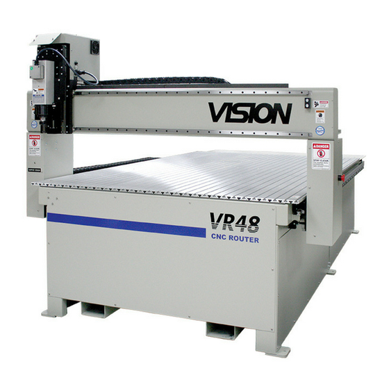
Vision VR48 Series 5
Installation Guide
© 2020 Vision Engraving & Routing Systems
mm__
mm__
This is ONLY the Installation Guide.
PLEASE review the complete User
Manual for your machine, which will be
installed on your computer after the
software installation is completed.
Revised: 5/14/2020
Advertisement
Table of Contents

Related Manuals for Vision Engraving & Routing Systems VR48 5 Series


Summary of Contents for Vision Engraving & Routing Systems VR48 5 Series
- Page 1 Vision VR48 Series 5 Installation Guide © 2020 Vision Engraving & Routing Systems Factory Settings Braille Inserter Offset X__________ Inches__ mm__ Y__________ Inches__ mm__ This is ONLY the Installation Guide. PLEASE review the complete User Manual for your machine, which will be installed on your computer after the software installation is completed.
- Page 2 Vision VR48 Series 5 Installation Guide © 2020 Vision Engraving & Routing Systems All rights reserved. No parts of this work may be reproduced in any form or by any means - graphic, electronic, or mechanical, including photocopying, recording, taping, or information storage and retrieval systems - without the written permission of the publisher.
-
Page 3: Table Of Contents
Contents Table of Contents Part I Introduction 1 Computer Requirements ........................... 4 2 Vision Software Security Device ........................... 5 3 General Electrical and Facility Requirements ........................... 6 4 Important VR48 Unloading Information ........................... 7 Part II Machine Setup 1 Layout Diagrams ........................... -
Page 4: Part I Introduction
Vision VR48 Introduction This guide contains information to prepare the owner of a Vision VR48 for the proper installation of their machine. It is the customer's responsibility to read through this guide and make sure the work area, electrical and computer requirements are met. If for any reason, there are questions about these requirements, please call your Vision representative as soon as possible. -
Page 5: Vision Software Security Device
Introduction Vision Software Security Device IMPORTANT: The Vision software is available in two versions; one with a USB dongle, and one that is "dongleless" and is loaded on to a USB Memory stick. If your machine was delivered with, or you currently have the silver, white/blue or orange software dongle, DO NOT LOSE IT! The Vision software will NOT run without the dongle plugged into the computer. -
Page 6: General Electrical And Facility Requirements
Vision VR48 General Electrical and Facility Requirements Machine Model Requirements VR48 Router - T-Slot Table With Standard 3 HP Router Head One 220 VAC 50 Amp Single Phase (Vision machine) With Optional 5 HP Router Head One 220 VAC 50 Amp Three Phase (Vision machine) VR48 Router - Vacuum Table With Standard 3 HP Router Head One 220 VAC 50 Amp Single Phase (Vision machine) -
Page 7: Important Vr48 Unloading Information
Introduction Important VR48 Unloading Information Unloading the Crate - IMPORTANT INFORMATION Please follow these guidelines when unloading the crated machine from the freight truck. The VR48 is shipped in a large framed crate with all accessories loaded under the machine. The crate presents a significant tip hazard when using lower capacity fork lifts. -
Page 8: Part Ii Machine Setup
Vision VR48 Machine Setup Layout Diagrams © 2020 Vision Engraving & Routing Systems... -
Page 9: Vr48 T-Slot Table
Machine Setup 2.1.1 VR48 T-Slot table © 2020 Vision Engraving & Routing Systems... -
Page 10: Vr48 Vacuum Table
Vision VR48 2.1.2 VR48 Vacuum table © 2020 Vision Engraving & Routing Systems... -
Page 11: Installation
Machine Setup Installation It is highly recommended that the computer being used to operate the Vision machine be connected to the internet. This will allow a Vision Technical Support representative to connect remotely to assist when needed. NOTE: This is only a recommendation and is not needed for daily use of the Vision equipment. 2.2.1 Electrical Requirements A qualified and licensed electrician must be used to complete all wiring and grounding of the... -
Page 12: Locating The Router
Vision VR48 2.2.2 Locating the Router A doorway of at least 80 inches wide and 80 inches high is required in order for the router to be moved into your facility. Locate machine indoors on a flat surface and on a solid foundation. Temperature must remain between 40°F and 85°F. -
Page 13: Connections
Machine Setup 2.2.3 Connections The Main Power Switch is located on the left side of the VR48. The main power supply is connected to the Main Electrical Box on the left side of the VR48. Remove the cover (if installed) and make the connections as shown below. Ground is connected to the bare wire and common leads are connected to the two shielded wires. - Page 14 Vision VR48 © 2020 Vision Engraving & Routing Systems...
- Page 15 Machine Setup On the front of the control box for VR48 Router, there are five connection ports; One is an Computer Ethernet port used to connect your computer or network to the on-board Series 5 Controller, the second two are for the Pendant, the fourth is a USB port to connect a computer to the optional DACS Camera System, and the fifth is to connect the Remote Start Switch for the Dust Collector System.
- Page 16 Vision VR48 © 2020 Vision Engraving & Routing Systems...
- Page 17 Machine Setup The Dust Collector Remote Start Switch will need to be connected. For ease of operation, a remote start switch and cables can be used to turn on the dust collector automatically when a job is being run. The supply for this connection is from Outlet #1 (220 VAC, Single Phase, 20 Amp or 110 VAC 25 Amp).
- Page 18 Vision VR48 © 2020 Vision Engraving & Routing Systems...
- Page 19 Machine Setup Wiring for this switch is shown below. The input and output wires should be connected as shown. Both input and output ground wires can be connected to the single GND location shown. The switch can be wall mounted at a location convenient for the user. The Remote Start Cable is connected to the Remote Start Port on the front of the machine's control box.
- Page 20 Vision VR48 © 2020 Vision Engraving & Routing Systems...
- Page 21 Machine Setup Vision Series 5 pendant (rear view) NOTE: If the emergency stop screen below appears on the LCD when the machine is powered on, then an emergency stop is triggered. This can either be one of the three emergency stop buttons on the table, the emergency stop button on the pendant or the electronics cabinet door is not installed.
- Page 22 Vision VR48 The machine is now connected. Please continue to the network setup section. © 2020 Vision Engraving & Routing Systems...
-
Page 23: Pendant Holder Installation
Machine Setup 2.2.4 Pendant Holder Installation The Touch Screen pendant holder for the VR48 can be mounted on the front of the machine. To install the Pendant Holder, remove the four screws on the machine and mount the holder to the machine as shown below. -
Page 24: Levelling The Machine
Vision VR48 2.2.5 Levelling the Machine Make sure the machine has been properly located at your work-site. It is not necessary to bolt your machine to the floor in your facility. However, a solid, stable foundation is required to support the machine's weight. There should be a leveling bolt in each of the four machine legs. -
Page 25: Scheduling Installation
Machine Setup 2.2.6 Scheduling Installation Please schedule an electrician to arrive and connect the electric to the router table, vacuum pump motor, and dust collector to the junction boxes and outlets prior to the first day of installation/machine orientation. Please contact Vision at 602-439-0600 or service@visionengravers.com if you or the electrician has any questions. -
Page 26: Vr48 Vacuum Pump Connection - Vacuum Table Model Only
Vision VR48 2.2.7 VR48 Vacuum Pump Connection - Vacuum Table Model Only The Main Vacuum Port for the VR48 is located at the foot of the machine. To connect the vacuum pump to the machine, use the supplied 3" diameter vacuum hose and connect one end to the vacuum pump and the other end to the Main Vacuum Port on the machine. - Page 27 Machine Setup The photo below shows the vacuum inlet, outlet, gauge, and filter. © 2020 Vision Engraving & Routing Systems...
- Page 28 Vision VR48 © 2020 Vision Engraving & Routing Systems...
-
Page 29: Network Connection
Machine Setup Network Connection NOTE - This following section is shown on a Windows 10 PC. For Windows 7 or Windows 8, the screens are slightly different. Plug the USB end of the USB to Ethernet adapter into any open USB port on the computer. Right click on the Windows network icon in the lower right corner of the Windows screen. - Page 30 Vision VR48 Select "Change adapter options". Right click on the Asix USB Ethernet connection. Select Properties. © 2020 Vision Engraving & Routing Systems...
- Page 31 Machine Setup Select "Internet Protocol Version 4 (TCP/IPv4). Select Properties. © 2020 Vision Engraving & Routing Systems...
- Page 32 Vision VR48 The screen below will appear. Enter the settings below. Select: Use the following IP address: Enter an IP address of: 192.168.100.100 Enter a Subnet mask of: 255.255.255.0 © 2020 Vision Engraving & Routing Systems...
- Page 33 Machine Setup Select OK. Plug one end of the network cable into the USB to Ethernet adaptor. Plug the other end of the network cable into the COMPUTER connection in the back of the Vision Series 5 controller. The network connection is now complete. Please continue to the network setup section. ©...
-
Page 34: Vision Mov Ui Software Installation
Vision VR48 Vision Mov UI Software Installation Power the Vision Series 5 controller on with the switch on the front. Insert the Vision USB dongle into the USB port on the computer. Navigate to the USB dongle in Windows File Explorer. Select the Start or Start.exe file to begin. - Page 35 Machine Setup Select Step 1 Setup Machine. © 2020 Vision Engraving & Routing Systems...
- Page 36 Vision VR48 Select Next on the "Prerequisites Setup Wizard" screen. NOTE: This screen will not appear if the Windows feature is already installed on the computer. Select Next on the "Prerequisites" installation screen. NOTE: This screen will not appear if the Windows feature is already installed on the computer. ©...
- Page 37 Machine Setup Select Next on the "Microsoft Vision C++ installation" screen. NOTE: This screen will not appear if the Windows feature is already installed on the computer. Select the I have read and accept the license terms box then select Install. NOTE: This screen will not appear if the Windows feature is already installed on the computer.
- Page 38 Vision VR48 Select Finish on the "Setup Complete" screen. NOTE: This screen will not appear if the Windows feature is already installed on the computer. Select Next on the "Welcome screen". © 2020 Vision Engraving & Routing Systems...
- Page 39 Machine Setup Select Next on the "Choose a file location" screen. Select Install on the "Begin installation" screen. © 2020 Vision Engraving & Routing Systems...
- Page 40 Vision VR48 Select Close on the "Successful Install" screen. The VisMovUI screen will appear. Select the Machine in the "Machines Discovered on Network" screen and click Select. © 2020 Vision Engraving & Routing Systems...
- Page 41 Machine Setup The VisMovUI program will appear. Select the Minimize button. The Vision Move UI program is now installed. Please continue to the network setup section. © 2020 Vision Engraving & Routing Systems...
-
Page 42: Vision Software Installation
Vision VR48 Vision Software Installation Insert the Vision USB dongle into the USB port on the computer. Navigate to the USB dongle in Windows File Explorer. Select the Start or Start.exe file to begin. Select 1612 and larger. © 2020 Vision Engraving & Routing Systems... - Page 43 Machine Setup Select Step 2 Install Vision Software. Select Next on the "Welcome" screen. © 2020 Vision Engraving & Routing Systems...
- Page 44 Vision VR48 Select Install on the "Ready to Install" screen. Select Finish on the "Complete Install" screen. © 2020 Vision Engraving & Routing Systems...
- Page 45 Machine Setup Select the language desired and select OK on the "Vision Pro install" screen. Make sure the USB dongle is installed and select Next on the "USB Flash Dongle" screen. © 2020 Vision Engraving & Routing Systems...
- Page 46 Vision VR48 Select Next on the "Vision 10 setup" screen. NOTE: The installation will display "Vision Pro 10 Setup", "Vision Expert 10 Setup" or "Vision Express 10 Setup" depending on which version has been purchased. Select the I accept the terms of the license agreement box then select Next on the "License Agreement"...
- Page 47 Machine Setup Select Next from the "Choose Destination Location" screen. NOTE: The installation folder will be either "C:\Vision Pro 10", "C:\Vision Expert 10" or "C:\Vision Express 10" depending on which version has been purchased. Select Next on the "Program Folder" screen. ©...
- Page 48 Vision VR48 The installation will continue. Select Vision S5 - Routers and select Next. © 2020 Vision Engraving & Routing Systems...
- Page 49 Machine Setup Select the VR48 Router S5 driver and select Next. NOTE: If ADA drivers or a center origin driver is needed, select them also. Select Continue on the "Font Installation" screen. © 2020 Vision Engraving & Routing Systems...
- Page 50 Vision VR48 The installation will search for Vision fonts. Select the disk drive to search for additional fonts that may be on the computer and select Yes. NOTE: Typically drive C:\ is selected. © 2020 Vision Engraving & Routing Systems...
- Page 51 Machine Setup The installation will search for additional fonts. NOTE: This may take a few minutes. Select OK on the "Font Installation Complete" screen. © 2020 Vision Engraving & Routing Systems...
- Page 52 Vision VR48 Select Finish to complete the installation. NOTE: The install may or may not ask to restart the computer. Select Exit from the initial screen. The Vision 10 software and Vision Manuals icon will now be on the Windows desktop. ©...
- Page 53 Machine Setup © 2020 Vision Engraving & Routing Systems...
Need help?
Do you have a question about the VR48 5 Series and is the answer not in the manual?
Questions and answers