Table of Contents
Advertisement
Advertisement
Table of Contents

Related Manuals for CYBEX R Series


Summary of Contents for CYBEX R Series
- Page 1 Cybex - R Series Recumbent Bike Assembly Instructions Part Number 1008128-0001 AB...
- Page 3 User and Service Documents Link Operation Manuals and other Product Information available at https://www.lftechsupport.com/web/document-library/documents https://www.lftechsupport.com/web/document-library/documents https://www.lftechsupport.com/web/document-library/documents https://www.lftechsupport.com/web/document-library/documents https://www.lftechsupport.com/web/document-library/documents https://www.lftechsupport.com/web/document-library/documents Trobareu el manual de funcionament i altra informació de producte a https://www.lftechsupport.com/web/document-library/documents Mae Llawlyfrau Gweithredu a Gwybodaeth Arall am Beiriannau ar gael yn https://www.lftechsupport.com/web/document-library/documents Die Betriebsanleitung und andere Produktinformationen erhalten Sie unter https://www.lftechsupport.com/web/document-library/documents...
-
Page 4: Table Of Contents
Cybex logo are registered trademarks of Cybex International, Inc. DISCLAIMER: Cybex International, Inc. makes no representations or warranties regarding the contents of this manual. We reserve the right to revise this document at any time or to make changes to the product described within it without notice or obligation to notify any person of such revisions or changes. -
Page 5: Getting Started
Caution: Any changes or modifications to this equipment could void the product warranty. Warning: Health-related injuries may result from incorrect or excessive use of exercise equipment. Cybex International, Inc. STRONGLY recommends seeing a physician for a complete medical exam before undertaking an exercise program, particularly if the user has a family history of high blood pressure or heart disease, is over the age of 45, smokes, has high cholesterol, is obese, or has not exercised regularly in the past year. - Page 6 Warning labels are shipped with every product and should be installed before product is used. Cybex International, Inc. is not responsible for missing or damaged warning labels. • Health and Environmental Regulations Warning - This product may contain chemicals known to the State of California to cause cancer, birth defects, or other reproductive harm.
-
Page 7: Consignes De Sécurité
Mise en garde :: Toute modification apportée à cet équipement pourrait en annuler la garantie. AVERTISSEMENT: Une utilisation incorrecte ou excessive de l'appareil peut entraîner des blessures. Cybex International, Inc. Recommande VIVEMENT aux utilisateurs de passer un examen médical complet avant d'entamer un programme d'entraînement, et tout particulièrement dans les cas suivants : antécédents... - Page 8 • Si certaines étiquettes d'avertissement sont manquantes ou endommagées, contactez immédiatement le Service à la clientèle. Nous vous en fournirons de nouvelles. Les étiquettes d'avertissement sont expédiées avec les appareils et doivent être installées avant utilisation de ces derniers. Cybex International, Inc. n'est pas responsable des étiquettes manquantes ou endommagées.
-
Page 9: Where To Place And How To Stabilize The Recumbent Bike
Where to Place and How to Stabilize the Recumbent Bike Read the entire manual before setting up the bike. After following all Safety Instructions, move the bike to the location where it will be used. Allow a clearance of 2 ft. (0.6 m) in the directions the bike is accessed from and 3 ft. (1 m) between the front or rear of the bike or any other objects. -
Page 10: Electrical Power Requirements (Applicable For Units Using External Power Supply)
3. Plug the cord into an AC outlet. Use only the external power supply provided by Cybex International, Inc. in order to insure against unsafe operation. Note: Units with the 50L console use a 12 VDC power supply. The 70T console uses a 24 VDC power supply. -
Page 11: Check For Console Power - 50L Console
The pedal action during workouts keeps the battery charged. Optional external power supply can be used. If the unit is externally powered, battery maintenance is automatic and pedaling is not required. Use only the power supply provided by Cybex International, Inc. to insure against unsafe operation. Page 11 of 25... -
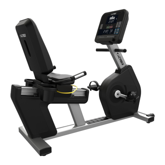
Page 12: Product Overview
Product Overview Product Features Item Description Qty. Console Wheel Leg Leveler Seat Adjustment Bar Cup Holder Contact Heart Rate Sensors Connections The following connection receptacle is located at the front of the bike. Item Description Qty. IR Connection HDMI Connection Coaxial Connection Power Input CAT5e Network / Ethernet... -
Page 13: How To Adjust Pedal Straps
How to Adjust Pedal Straps The bike pedal straps keep the user’s shoes on the pedals during a workout. The straps should fit comfortably but tight enough to prevent shoes from slipping at any point in the pedaling rotation. A user should test and adjust the tightness of the straps before starting a workout. -
Page 14: How To Adjust Seat
How to Adjust Seat A properly adjusted seat is important in any bike-oriented exercise activity. If the seat is too close, excessive strain will be placed on the knees and quadriceps muscles. If the seat is too far, the resulting reaching action will irritate the feet, ankles, hips and knees. -
Page 15: Service And Technical Data
Service and Technical Data Preventive Maintenance Tips Note: Safety of the equipment can be maintained only if the equipment is examined regularly for damage or wear. Keep the equipment out of use until defective parts are repaired or replaced. Pay special attention to parts that are subject to wear, as outlined below. -
Page 16: Preventive Maintenance Schedule
Preventive Maintenance Schedule Item Weekly Monthly Biannually Console Overlays Clean Inspect Bottle Holders / Accessory Trays Clean Inspect Console Mounting Bolts Inspect Hardware Inspect Frame / Seat Post Clean Inspect Plastic Covers Clean Inspect Lifepulse Sensors Clean / Inspect Leg Levelers Inspect / Adjust Pedals / Straps Clean... -
Page 17: Troubleshoot The Lifepulse ™ Sensors
2. Locate and write down the serial number of the unit which is located on the top right of the front stabilizer. 3. Contact Cybex International, Inc. Customer Support Services at http://www.lifefitness.com. Page 17 of 25... -
Page 18: Assembly
Assembly Hardware and Required Tools Hardware Item Description Qty. M8 X 20 Flange Hex Head Cap Screw M8 X 40 Flange Hex Head Cap Screw Washer, M8 M6 X 16 Phillips Pan Head Screw Grommet M5 X 14 Phillips Pan Head Screw M4.2 X 19 Phillips Pan Head Screw Required Tools: •... -
Page 19: Attach Cup Holders
Attach Cup Holders Secure cup holders with four screws. Item Description Qty. Cup Holder, Left Cup Holder, Right M6 X 16 Phillips Head Pan Screw 4 Nm (35 in. lbs.) Attach Handlebars 1. Attach handlebars using four screws. Item Description Qty. -
Page 20: Attach Lower Seat Back Covers
Attach Lower Seat Back Covers 1. Attach front lower seat back cover with two screws. Item Description Qty. Lower Seat Back Cover, Front Lower Seat Back Cover, Rear M6 X 16 Phillips Head Pan Screw 4 Nm (35 in. lbs.) 2. -
Page 21: Attach Monocolumn To Base
Attach Monocolumn to Base Caution: Remove any protective covering / tape from the monocolumn and console support weldment prior to attaching to base! Failure to remove the protective covering can cause improper grounding! Item Description Qty. Monocolumn M8 X 20 Flange Head Cap Screw 34 Nm (25.1 ft. -
Page 22: Base To Console Cable Connections - 50L
Base to Console Cable Connections - 50L Item Description Qty. Console to Base Power Base Signal Handlebar Keypad Switches (Resistance) Lifepulse Base to Console Cable Connections - 70T Item Description Qty. External Power Cable PCB to Console Cable Coaxial Cable CAT5e HDMI (optional) IR (optional) -
Page 23: Attach Wheel Covers
3. Use four screws to secure rear console shroud assembly through monocolumn into console. Item Description Rear Console Shroud Assembly M5 X 14 Phillips Pan Head Screw 1.5 Nm (1.1 ft. lbs.) Attach Wheel Covers Press wheel covers into mounting holes and over wheel mounting bolts. Item Description Qty. -
Page 24: Specifications
Specifications Specifications Designed Use Heavy / Commercial EN ISO 20957 Class SA Maximum User Weight 400 lbs. / 181 kg Pedal Size 5 in. x 5.5 in. / 127 mm x 140 mm Drive Type Belt • Units that are only equipped with the 50L console are self powered. •... - Page 25 Columbia Center III - 9525 West Bryn Mawr Ave, Rosemont, IL 60018 • 800-351-3737 • 847-288-3700 • FAX 800-216-8893 www.cybexintl.com...
Need help?
Do you have a question about the R Series and is the answer not in the manual?
Questions and answers