Table of Contents
Advertisement
Advertisement
Table of Contents

Subscribe to Our Youtube Channel
Related Manuals for CYBEX R Series


Summary of Contents for CYBEX R Series
- Page 1 R Series Arc Trainer Assembly Instructions Part Number 1008301-0001 AC...
- Page 3 User and Service Documents Link Operation Manuals and other Product Information available at https://www.lftechsupport.com/web/document-library/documents https://www.lftechsupport.com/web/document-library/documents https://www.lftechsupport.com/web/document-library/documents https://www.lftechsupport.com/web/document-library/documents https://www.lftechsupport.com/web/document-library/documents https://www.lftechsupport.com/web/document-library/documents Trobareu el manual de funcionament i altra informació de producte a https://www.lftechsupport.com/web/document-library/documents Mae Llawlyfrau Gweithredu a Gwybodaeth Arall am Beiriannau ar gael yn https://www.lftechsupport.com/web/document-library/documents Die Betriebsanleitung und andere Produktinformationen erhalten Sie unter https://www.lftechsupport.com/web/document-library/documents...
- Page 4 International Offices AMERICAS United Kingdom North America Life Fitness UK LTD All Other EMEA Countries and Distributor Business EMEA* Cybex International Inc. Queen Adelaide Bijdorpplein 25-31 Columbia Centre III Ely, Cambs, CB7 4UB 2992 LB Barendrecht 9525 West Bryn Mawr Avenue Telephone: General Office (+44) 1353.666017...
-
Page 5: Table Of Contents
Product Overview Product Features........................13 Mounting and Dismounting the Arc Trainer................13 How to Use the Arc Trainer.......................14 Assembly Assembly Procedure - R Series Lower Body................15 Assembly Procedure - R Series Total Body................27 Service and Technical Data Preventive Maintenance Tips....................42 Approved and Compatible Cleaners..................42... -
Page 6: Getting Started
Please take special note of the following safety instructions and important points prior to choosing a location and beginning assembly of the product. WARNING: Health-related injuries may result from incorrect or excessive use of exercise equipment. Cybex STRONGLY recommends seeing a physician for a complete medical exam before undertaking an exercise program, particularly if the user has a family history of high blood pressure or heart disease, is over the age of 45, smokes, has high cholesterol, is obese, or has not exercised regularly in the past year. - Page 7 Warning labels are shipped with every product and should be installed before product is used. Cybex is not responsible for missing or damaged warning labels. NOTE: This equipment has been tested and found to comply with the limits for a Class A digital device, pursuant to part 15 of the FCC rules.
-
Page 8: Consignes De Sécurité
Prêtez une attention toute particulière aux instructions de sécurité ci-dessous avant de choisir un emplacement et de commencer à assembler votre produit. AVERTISSEMENT: Une utilisation incorrecte ou excessive de l'appareil peut entraîner des blessures. Cybex Recommande VIVEMENT aux utilisateurs de passer un examen médical complet avant d'entamer un programme d'entraînement, et tout particulièrement dans les cas suivants : antécédents familiaux... - Page 9 • Si certaines étiquettes d’avertissement sont manquantes ou endommagées, contactez immédiatement le Service à la clientèle. Nous vous en fournirons de nouvelles. Les étiquettes d’avertissement sont expédiées avec les appareils et doivent être installées avant utilisation de ces derniers. Cybex n’est pas responsable des étiquettes manquantes ou endommagées.
-
Page 10: Setup
• Free area for access to unit and emergency dismount. Minimum clearance is 23.6 inches (0.6 meters). • Adjacent units may share the free area. Free Area - R Series Lower Body 23.6”, 0.6m Free Area - R Series Total Body 23.6”, 0.6m... -
Page 11: Install External Power Supply
Console Supply Voltage Frequency Output Voltage Output Current 50L with Attachable TV 95 - 264 VAC 47 - 63 Hz 12 VDC 95 - 264 VAC 47 - 63 Hz 24 VDC 3.5 A Outlet Voltage Commercial Units Outlet & Breaker (Amps) 120 VAC 20 (no more than 10 units per breaker) 230 VAC... -
Page 12: Check For Console Power
Cable TV Hook Up The console can receive both analog and digital signals. CYBEX is not responsible for the installation of CATV service or components required for the delivery of CATV service. An external TV signal input via a 75-ohm coaxial cable must be present before TV setup can occur. -
Page 13: Product Overview
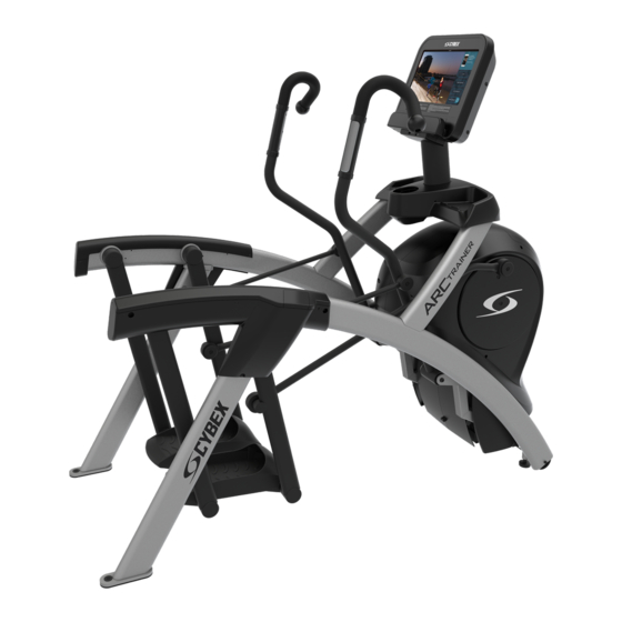
Product Overview Product Features R Series Lower Body Item Description Console Accessory Trays Contact Heart Rate Sensors Cup Holder Side Handles Leg Levelers R Series Total Body Item Description Console Accessory Trays Cup Holder Contact Heart Rate Sensors Leg Levelers Mounting and Dismounting the Arc Trainer To mount, step one foot at a time atop each of the foot plates. -
Page 14: How To Use The Arc Trainer
To begin exercise, push down and back into the pedals. Since the Arc Trainer pedals travel back and forth along an arc (not in a circle or ellipse), there is no ‘forward’ or ‘backward’ motion. To dismount, slowly bring the pedals to a stop. Grasp the stationary handles or part of the frame to assist in stepping off the foot plate, back and away from the machine. -
Page 15: Assembly
Assembly Assembly Procedure - R Series Lower Body Two people will be required for this procedure. TIP: Read and understand all instructions thoroughly before assembling this unit. Check all items carefully. If there is damage, see the Customer Service section of this manual for proper procedure to return, replace, or reorder parts. - Page 16 Hardware Item Description Quantity 7/32” Allen Wrench Grommet, Nylon, Long Grommet, Nylon, Short Screw, Pan Head Phillips, Tap 10-12 x 2" Screw, Pan Head Phillips, M4.2 x 0.7 x 19 Screw, Pan Head Phillips, 6 x .50” Screw, Pan Head Phillips, 8-16 x .50” Screw, Pan Head Phillips, 10-24 x .75"...
- Page 17 Hardware Pack 1 Hardware Pack 2 Tools Required • Phillips screwdriver • Stubby Phillips screwdriver • 6 mm Allen wrench Page 17 of 47...
- Page 18 • 7 mm Allen wrench • 7/32” Allen wrench • 17 mm Open end wrench • 1/2” Open end wrench • 9/16” Open end wrench Lift and Move Unit 1. Remove lag bolts and shipping supports. Keep package material on linkage arms at this time. This will protect the paint from scratching during assembly.
- Page 19 Install Cables to Console Plug the console cables into the console. 50L Console Item Description Cable, Console to Base Power Cable, Lifepulse Cable, Base Signal Cable, Heart Rate and Keypad Switches 70T Console Item Description Cable, HDMI Cable, Ethernet Cable, Coax Cable, External Power Cable, PCB to Console Power Cable, IR...
- Page 20 4. Place console into position on console weldment. NOTE: Do not pinch cables while lowering the console. Item Description Console Assembly Weldment, Console Cover, Console Back Screw, Pan Head Phillips, M5 x 0.8 x 14 Grounding Screw, Pan Head Phillips, M5 x 0.8 x 14 Media Cables 5.
- Page 21 Install Console Cables to Base (Advanced Cabling) This procedure applies to the Advanced Cabling option. 1. Plug upper display cable into lower display cable. Item Description Cable, HDMI (previously routed to console) Cable, Ethernet (previously routed to console) Cable, Coax (previously routed to console) Cable, IR (previously routed to console)
- Page 22 Item Description Qty. Accessory Tray Top Accessory Tray Base Screw, Pan Head Phillips, 8-16 x .50" Install Accessory Tray Bottom 1. Install the grommet to the frame. Item Description Qty. Grommet, Nylon, Long Frame 2. Install screws securing the accessory tray bottom to the accessory tray top using a Phillips screwdriver. 3.
- Page 23 Item Description Locknut, M10 x 1.50 Spacer Side Handle, Left 2. Install the left side handle and three locknuts using 17mm open-end wrench and 6mm Allen wrench. Ensure upper roll pin enters hole in frame. 3. Install screws securing left lower rear cover to frame using a Phillips screwdriver. Item Description Cover, Rear, Lower, Left...
- Page 24 8. Repeat steps 1 through 7 for the right side. Install Foot Pads Have one person lift the unit while a second person places a foot pad under each of the two back feet. NOTE: Cybex requires that foot pads be installed to prevent rocking. Item Description...
- Page 25 Visually Inspect Unit 1. Remove any packing material from unit. 2. Examine the unit to ensure that the assembly is correct and complete. Level Unit This procedure will level the unit by evenly adjusting the weight on the rear feet. Leveling the unit will eliminate rocking during use.
- Page 26 4. Adjust the weight of the rear feet using a 1/2” open-end wrench. • If the left rear foot lifts up easier, Adjust the right leveling foot nut down. • If the right rear foot lifts up easier, Adjust the left leveling foot nut down. Left leveling foot shown Item Description...
-
Page 27: Assembly Procedure - R Series Total Body
Assembly Procedure - R Series Total Body Two people will be required for this procedure. TIP: Read and understand all instructions thoroughly before assembling this unit. Check all items carefully. If there is damage, see the Customer Service section of this manual for proper procedure to return, replace, or reorder parts. - Page 28 Hardware Item Description Quantity 3/16” Allen Wrench 7/32” Allen Wrench Flange Spacer Washer, Flat .281 ID x .500 OD x .062” Grommet, Nylon, Long Grommet, Nylon, Short Screw, Pan Head Phillips, Tap 10-12 x 2" Screw, Pan Head Phillips, M4.2 x 0.7 x 19 Screw, Pan Head Phillips, 6 x .50”...
- Page 29 Item Description Quantity Loctite #242 Screw, Socket Head, .375-16 x 2.5" Locknut, .375-16 Nylon Screw, Pan Head Phillips, M5 x 0.8 x 14 Hardware Pack 1 Hardware Pack 2 Page 29 of 47...
- Page 30 Tools Required • Phillips screwdriver • Stubby Phillips screwdriver • 6 mm Allen wrench • 7 mm Allen wrench • 3/16” Allen wrench • 7/32” Allen wrench (2) • 17 mm Open end wrench • 1/2” Open end wrench • 9/16” Open end wrench Lift and Move Unit 1.
- Page 31 4. Move unit to intended location. 5. Lower rear support legs. Install Console Weldment 1. Place console weldment into position on frame. Item Description Weldment, Console Frame Bracket, Lower Screw, Socket Head, .375-16 x 2.5" Locknut, 375-16 Nylon 2. Insert (from underneath) four bolts and lower bracket into frame and console weldment. 3.
- Page 32 Install Cables to Console Plug the console cables into the console. 50L Console Item Description Cable, Console to Base Power Cable, Lifepulse Cable, Base Signal Cable, Heart Rate and Keypad Switches 70T Console Item Description Cable, HDMI Cable, Ethernet Cable, Coax Cable, External Power Cable, PCB to Console Power Cable, IR...
- Page 33 4. Place console into position on console weldment. NOTE: Do not pinch cables while lowering the console. Item Description Console Assembly Weldment, Console Cover, Console Back Screw, Pan Head Phillips, M5 x 0.8 x 14 Grounding Screw, Pan Head Phillips, M5 x 0.8 x 14 Media Cables 5.
- Page 34 Install Console Cables to Base (Advanced Cabling) This procedure applies to the Advanced Cabling option. 1. Plug upper display cable into lower display cable. Item Description Cable, HDMI (previously routed to console) Cable, Ethernet (previously routed to console) Cable, Coax (previously routed to console) Cable, IR (previously routed to console)
- Page 35 Item Description Qty. Accessory Tray Top Accessory Tray Base Screw, Pan Head Phillips, 8-16 x .50" Install Accessory Tray Bottom 1. Install the grommet to the frame. Item Description Qty. Grommet, Nylon, Long Frame 2. Install screws securing the accessory tray bottom to the accessory tray top using a Phillips screwdriver. 3.
- Page 36 Item Description Cover, Rear, Lower, Left Screw, Pan Head Phillips, 10-24 x .75" 2. Install grommets to left top rear cover. Item Description Grommet, Nylon, Short Cover, Rear, Top, Left 3. Install screws into grommets securing left lower rear cover to left top rear cover using a Phillips screwdriver. Item Description Screw, Pan Head Phillips, M4.2 x...
- Page 37 Item Description Handle Assembly, Left Handle Assembly, Right 1. Remove a screw and washer from the left handle assembly using two 7/32” Allen wrenches. Item Description Screw Washer Handle Assembly, Left Pivot Pin Assembly Loctite #242 2. Slide pivot pin assembly out and remove left handle assembly. 3.
- Page 38 8. Slide pivot pin assembly out and remove right handle assembly. 9. Rotate right handle assembly 180 degrees. 10. Apply Loctite to threads inside the pivot pin and screw. 11. Place right handle assembly in position and slide pivot pin assembly back in place. 12.
- Page 39 3. Repeat steps to install heart rate cable on opposite handle. Install Foot Pads Have one person lift the unit while a second person places a foot pad under each of the two back feet. NOTE: Cybex requires that foot pads be installed to prevent rocking. Page 39 of 47...
- Page 40 Item Description Foot Pads Visually Inspect Unit 1. Remove any packing material from unit. 2. Examine the unit to ensure that the assembly is correct and complete. Level Unit This procedure will level the unit by evenly adjusting the weight on the rear feet. Leveling the unit will eliminate rocking during use.
- Page 41 3. Grasp the other rear cover and slowly lift the rear foot off the floor. Lower rear foot to the floor. Make note of either rear foot lifting off the floor easier than the other. If both rear feet lift off the floor evenly, secure both leveling foot jam nuts against the frame post using a 9/16” open-end wrench.
-
Page 42: Service And Technical Data
Service and Technical Data Preventive Maintenance Tips CYBEX products are backed by the engineering excellence and reliability of CYBEX and are one of the most rugged and trouble-free pieces of exercise equipment on the market today. NOTE: Safety of the equipment can be maintained only if the equipment is examined regularly for damage or wear. -
Page 43: Troubleshooting The Polar ® Heart Rate Chest Strap
Item Weekly Monthly Annually Frames Clean Inspect Plastic Covers Clean Inspect Inspect Lifepulse Sensors Clean / Inspect Foot Plates Clean Inspect Leg Levelers Inspect / Adjust ® Troubleshooting the Polar Heart Rate Chest Strap Heart rate reading is erratic or absent entirely Probable Cause Corrective Action Belt transmitter electrodes are not wet enough to pick up accurate... - Page 44 Description Qty. Screw Front Access Cover 2. Remove access cover. WARNING: Burn hazard. Do not touch flywheel until cool. Inspect Drive Belts There are two drive belts that may become loose, worn or cracked. Unless the belts have been removed and not replaced properly, it is unlikely the belts will come loose or need to be re-tensioned.
-
Page 45: How To Obtain Product Service
How to Obtain Product Service 1. Verify the symptom and review the operating instructions. The problem may be unfamiliarity with the product and its features and workouts. 2. Locate and write down the serial number of the unit which is located on the front of the unit. Write down the software version if possible. -
Page 46: Specifications
Specifications R Series - Specifications R Series Lower Body Classification EN ISO 20957 Class S (Studio) Accuracy Assembled Length 76.25” (194 cm) Assembled Width 36.28” (92 cm) Assembled Height 62.5” (159 cm) Product Weight 412 lbs. (187 kg.) Shipping Weight 485-490 lbs. - Page 48 Columbia Center III - 9525 West Bryn Mawr Ave, Rosemont, IL 60018 • 800-351-3737 • 847-288-3700 • FAX 800-216-8893 www.cybexintl.com...
Need help?
Do you have a question about the R Series and is the answer not in the manual?
Questions and answers