Table of Contents
Advertisement
Quick Links
UWAGA!!
● NaleŜy dokładnie zapoznać się z poniŜsza instrukcją przed
instalacją lub uŜywaniem urządzenia.
● By uniknąć uszkodzęń i zagroŜenia Ŝycia urządzenia
te powinny być instalowane przez wykwalifikowany personel,
i w zgodzie z odpowienimi przepisami.
● Przed pracami serwisowymi, naleŜy odłączyć wszystkie napięcia od wejść
pomiarowych i zasilania pomocniczego oraz zewrzeć zaciski przekładnika
prądowego.
● Produkty zaprezentowane w poniŜszym dokumencie mogą zostać zmienione
lub ulepszone bez konieczności wcześniejszego informowania o tym.
● Dane techniczne oraz opisy oddają w jak najdokładniejszy sposób posiadaną
przez nas wiedzę, jednak nie bierzemy odpowiedzialności za ewentualne błędy,
braki oraz sytuacje awaryjne.
● W układzie naleŜy zamontować rozłącznik (wyłącznik), który musi znajdować
się niedaleko urządzenia i być łatwo dostępny dla operatora. Musi spełniać wymogi
następujących norm: IEC/ EN 61010-1 § 6.12.2.1.
● NaleŜy umieszczać urządzenie w obudowie lub szafie o minimalnym stopniu
ochrony IP40.
● NaleŜy czyścić urządzenie delikatną suchą szmatką, nie naleŜy uŜywać środków
ściernych, płynnych detergentów lub rozpuszczalników..
Spis treści
Wprowadzenie
Moduły EXM dedykowane są do produktów z moŜliwością rozszerzenia
przez łącze podczerwieni i zostały zaprojektowane by zwiększyć
moŜliwość typu podłączenia, dostępnoćć wejść/wyjść i zapamiętywanie
i analizę pomiarów z urządzenia do którego jest podłączony. EXM1010
umoŜliwia podłączenie miernika przez port USB i moŜe być podłączony do
kaŜdego z urządzeń Lovato, które wyposaŜone jest w komunikację przez
podczerwień. Przyłączenia dokonuje się szybko do jednostki bazowej lub
juŜ
zamontowanego
modułu.
automatycznie rozpozna typ modułu EXM,
Opis
Obudowa modułowa 2U (36mm) do montaŜu na szynie DIN
•
Podwójny port podczerwieni
•
Port komunikacji USB, typu: wirtualny COM
•
2 wskaźniki LED
•
Automatyczne rozpoznanie przez urządzenie
•
Ustawianie parametrów (COM) przez menu urządzenia
•
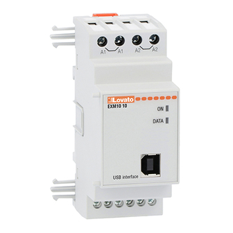
EXM10 10
Moduł rozszerzeń
Interfejs USB
INSTRUKCJA OBSŁUGI
Strona
1
1
2
4
4
4
4
5
5
6
Po
podłączeniu
zasilania
Doc: MHIT200A0608_EXM1010
WARNING!
• Carefully read the manual before the installation or use.
• This equipment is to be installed by qualified personnel,
complying to current standards, to avoid damages or safety
hazards.
● Remove the dangerous voltage from the product before any maintenance
operation on it.
● Products illustrated herein are subject to alteration and changes without prior
notice.
● Technical data and descriptions in the documentation are accurate, to the best
of our knowledge, but no liabilities for errors, omissions or contingencies arising
therefrom are accepted.
● A circuit breaker must be included in the electrical installation of the building. It
must be installed close by the equipment and within easy reach of the operator.
It must be marked as the disconnecting device of the equipment:
IEC /EN 61010-1 § 6.12.2.1
● Fit the instrument in an enclosure or cabinet with minimum IP40 degree
protection.
● Clean the instrument with a soft dry cloth, do not use abrasives, liquid
detergents or solvents
Index
Introduction
The EXM units for Lovato infrared expandable products, are designed
and developed to enhance the functions of connectivity, I/O, memory and
analysis of the instrument to which it is connected.
The EXM10 10 implements the USB serial interface and can be
connected to any Lovato product fitted of infrared optical interface.
The connection will be done simply approaching the units to the base
instrument or to another module.
układ
At the power on of the system, the instrument will automatically
recognize the units, the EXM communication setup and output
functionality will be done directly from the proper instrument menu in an
easy way.
Description
Modular DIN-rail housing, 2U (36mm wide).
•
Double infrared connection port
•
Virtual COM port USB serial interface
•
2 Indication LED
•
Automatically recognition from the instrument to which is connected
•
EXM configuration from the proper instrument menu
•
10/09/2009
EXM10 10
Expansion units
USB interface
INSTRUCTIONS MANUAL
Page
1
1
2
4
4
4
4
5
5
6
s. 1 / 6
Advertisement
Table of Contents

Subscribe to Our Youtube Channel
Related Manuals for LOVATO ELECTRIC EXM10 10


Summary of Contents for LOVATO ELECTRIC EXM10 10
-
Page 1: Table Of Contents
EXM1010 The EXM10 10 implements the USB serial interface and can be umoŜliwia podłączenie miernika przez port USB i moŜe być podłączony do connected to any Lovato product fitted of infrared optical interface. -
Page 2: Instalacja Sterowników Usb
Insert the driver CD present on the EXM package on the PC. do modułu EXM. Następnie naleŜy podłączyć moduł EXM10 10 do komputera Connect the EXM10 10 to the PC using the USB cable (with uŜywając kabla USB (moduł musi być zasilony). the module powered). - Page 3 NaleŜy upewnić się, Ŝe ścieŜka dostępu do sterowników jest Verify that the drivers path is again the previous indicated in taka sama jak wskazano w kroku 4 i kliknąć <Dalej>. the step #4 and go to the next step. Wait the end of the drivers installation and click on the NaleŜy poczekać...
-
Page 4: Funkcje Wskaźników Led
Kompatybilność z produktami Lovato Lovato products compatibility Moduł rozszerzeń EXM10 10 moŜe być podłączony do wszystkich EXM10 10 expansion units can be connected to any Lovato product fitted urządzeń Lovato posiadających moŜliwość komunikacji przez port of optical infrared communication port. -
Page 5: Schematy Podłączeń
Schematy podłączęń Wiring diagrams UWAGA: zaciski A1 i A1 są wewnętrznie połączone ze sobą, ATTENTION: terminals A1 and A1 are internally connected tak samo zaciski A2 i A2. Wolne zaciski A1 i A2 są przeznaczone do together and the same is for A2 and A2. The free terminals A1 and zasilania kolejnego modułu serii EXM (Max 3). -
Page 6: Dane Techniczne
Dane techniczne Technical characteristics Zasilanie pomocnicze Auxiliary supply Napięcie znamionowe Us 100 - 240V~ Nominal voltage Us 100 - 240V~ 110 - 250V= 110 - 250V= Zakres napięcia pracy 85 - 264V~ Operating voltage range 85 - 264V~ 93,5 - 300V= 93,5 - 300V= Częstotliwość...
Need help?
Do you have a question about the EXM10 10 and is the answer not in the manual?
Questions and answers