Table of Contents
Advertisement
Quick Links
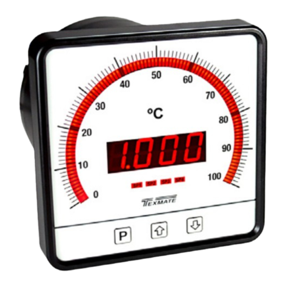
LEOPARD
FAMILY
Specifications
Input Specs: ������������������ Depends on Input signal conditioner
A/D Converter: �������������� 14 bit single slope
Accuracy: ���������������������� ±(0�05% of reading + 2 counts)
Temp. Coeff�: ����������������� 100 ppm/°C (Typical)
Warm up time: ��������������� 2 minutes
Conversion Rate: ���������� 10 conversions per second (Typical)
Digital Display: �������������� 4 digit 0.56" LED red (std), green (optn)
Range -1999 to 9999 counts�
Bargraph Display: ��������� 101 segment 235º circular red (standard),
Green (optional) or tricolor (optional) LED�
Polarity: ������������������������� Assumed positive� Displays - negative
Decimal Selection: �������� Front panel button selectable, X•X•X•X•
Positive Overrange: ������ Bargraph and top segments of digital display
flash�
Negative Overrange: ���� First segment of bargraph and bottom seg-
ments of digital display flash�
Relay Output: ���������������� Two 9 Amp Form C relays, two 4 Amp Form
A relays or 4 x 4 Amp Form A relays
Analog Output: ������������� Isolated 16 bit user scalable mA or V
OIC (mA out) �������������� 4-20 mA @ 0 to 500٠max loop resistance
OIV (volts out) �������������� 0-10 V DC @ 500 ٠or higher resistance
Power Supply: ��������������� AC/DC Auto sensing wide range supply
PS1 (std) �������������������� 85-265 VAC / 95-300 VDC, 50-400Hz 4.2W
PS2 ����������������������������� 18-48 VAC / 10-72 VDC, 50-400Hz 4�2W
Operating Temp�: ���������� 0 to 60°C
Storage Temp: ��������������� -20°C to 70°C
Relative Humidity: �������� 95% (non condensing)
Case Dimensions: �������� Bezel (4.48"x4.48") 113.8x113.8mm
Depth behind bezel (4.23") 107.46 mm
Plus (0�48") 12�24 mm for connectors
Weight: ��������������������������� 16 oz�, 1lb 4 oz when packed
Bargraph Color Programming Mode . . . . . . . . 9
Case Dimensions . . . . . . . . . . . . . . . . . . . . . . 11
Component Layout. . . . . . . . . . . . . . . . . . . . . 11
Connector Pinouts . . . . . . . . . . . . . . . . . . . 10-11
Controls and Indicators . . . . . . . . . . . . . . . . . . 2
Decimal Point and Brightness Selection . . . . . 5
CL-B101D40-TCRTD Manual (d0099)
CL-B101D40-TCRTD
Smart 101 segment 4 digit LED Tricolor or Mono-color
digital bargraph controller with four fully programmable
set points for J, K, R, and T type thermocouples and
0.56" LEDs
Table of Contents
Functional Diagram . . . . . . . . . . . . . . . . . . . . 10
General Features . . . . . . . . . . . . . . . . . . . . . . . 1
Input Module Calibration Procedures . . . . . . 12
Ordering Information . . . . . . . . . . . . . . . . . . . 13
Pin Descriptions . . . . . . . . . . . . . . . . . . . . . . . 10
RTD inputs in a switchboard style case.
General Features
•
External transmitters or signal conditioners can be eliminated by
direct connection of the sensor output to Plug-in Input Signal
Conditioners- available are thermocouples (J, K, R and T types)
or RTD (Pt-100. 385 and 392 curves. 3 wire/4wire). Digitally
Linearized.
•
Optional isolated 16 bit analog output. User or factory scalable to 4
to 20 mA, 0 to 20 mA or 0 to 10 V across any desired digital span
from ± one count to the full scale range of - 1999 to 9999 (12000
counts).
•
A Programmable Tricolor (Red-Green-Orange) or mono color (red or
green), 101 segment high brightness bargraph.
•
Red 4-digit LED display with a range of -1999 to 9999
(12000 counts). Optional green digital display.
•
Front panel LED annunciators provide indication of setpoint status.
•
Two 9 Amp Form C, and two 4 Amp Form A or 4 x 4 Amp Form A
relays available.
•
Auto-sensing AC/DC power supply. For voltages between
85-265 V AC / 95-300 V DC (PS1) or 18-48 V AC / 10-72 V DC
(PS2).
•
Provision to connect an external programming lockout switch.
•
Provision for external DIM switch to reduce the brightest
display setting by 50%.
•
Automatic intelligent averaging, smooths noisy signals while
providing a fast display response to real level changes.
Software Features
• The bargraph can display, full
scale, any desired portion of
the digital reading.
• Setpoint 1 has delay-on-make
and delay-on-break plus
a special "pump on pump
off" mode that creates a
Hysteresis Band between SP1
and SP2.
Programming Conventions. . . . . . . . . . . . . . . . 2
Setpoint Setting & Relay Conf. Mode . . . . . . 8-9
Software Features . . . . . . . . . . . . . . . . . . . . . . 1
Software Logic Tree . . . . . . . . . . . . . . . . . . . . . 3
Specifications. . . . . . . . . . . . . . . . . . . . . . . . . . 1
Thermocouple and RTD Type Selection Mode. . . . . .4
• Four programmable setpoints
with adjustable Hysteresis.•
Bargraph center zero function.
• Relay activation can be select-
ed to occur above (hi) or below
(Lo) each setpoint.
• Digital display blanking.
• Decimal point setting.
• Four-level brightness control
Page 1
Advertisement
Table of Contents

Related Manuals for Texmate CL-B101D40-TCRTD


Summary of Contents for Texmate CL-B101D40-TCRTD
-
Page 1: Table Of Contents
Pin Descriptions ..... . . 10 Thermocouple and RTD Type Selection Mode..4 CL-B101D40-TCRTD Manual (d0099) Page 1... -
Page 2: Controls And Indicators
If an X appears through a digit, it means that gram indicates that programming branch any number displayed in that digit is not rel- will appear only when a particular option is evant to the function being explained. present. Page 2 CL-B101D40-TCRTD Manual (d0099) -
Page 3: Software Logic Tree
Software Logic Tree Software Version is Displayed on Power-up The CL-B101D40-TCRTD is an intelligent bargraph meter with a hierarchical software structure designed for easy programming When power is applied, all segments of the bargraph and and operation, as shown below in the software logic tree. -
Page 4: Thermocouple And Rtd Type Selection Mode
Bargraph Display Page 5 -200 to 800°C -200 to 1470°F 100Ω RTD (392 curve) 0.1° -199.9 to 530.0°C -199.9 to 999.9°F Input Module Calibration Procedure See page 12 for the Calibration instructions of each Input Module type. Page 4 CL-B101D40-TCRTD Manual (d0099) -
Page 5: Decimal Point And Brightness Selection
Note: If at this point, the display skips directly to STEP G and for Analog Range Output or toggles between [Cto] and [oFF], the software is detecting Bargraph Center Point Display Mode Selection that the optional analog output hardware is NOT installed. on Page 6 CL-B101D40-TCRTD Manual (d0099) Page 5... -
Page 6: Bargraph Center Point Display Mode Selection
If the digital display is selected to be off, pressing any button to make programming changes or to view setpoints activates the digital display. When the procedure is complete, the digital display will then automatically switch off. The Display/Bargraph settings are now complete. Operational Display Page 6 CL-B101D40-TCRTD Manual (d0099) -
Page 7: Two Point Analog Range Setting & Calibration
AnHi and AnLo. However, the analog output can linearly rise above the chi value set for digital readings outside the digital span selected. See Digital Span Selection on page 6. CL-B101D40-TCRTD Manual (d0099) Page 7... -
Page 8: Setpoint Setting & Relay Conf. Mode
Hysteresis to be ON or OFF� 2) Press the button� Display toggles between [rLYS] and the previous relay setting� STEP L Please Continue On Next Page. To Step M of Setpoint Setting and Relay Configuration Page 9 Page 8 CL-B101D40-TCRTD Manual (d0099) -
Page 9: Bargraph Color Programming Mode
[grn], [oran] or [red] Operational Display 2) Press the button. The meter exits the setpoint mode and returns to the operational display. The Bargraph Color programming mode is now complete. CL-B101D40-TCRTD Manual (d0099) Page 9... -
Page 10: Connector Pinouts
9 Amp Form C and dual 4 Amp Form A relays� An analog output module is also shown as installed� The CL-B101D40-TCRTD uses plug-in type screw terminal con- nectors for all input and output connections� The power supply connections (pins 14 and 15) have a unique plug and socket out- Input Signal –... -
Page 11: Component Layout
OR53 210mA 210mA 210mA OR33 OR54 210mA 210mA 210mA 210mA OR34 Component Layout Component Layout Relay Relay Output Output Module Module Carrier Carrier Board Board Display Board Analog Output Module Main Input Signal Board Conditioner CL-B101D40-TCRTD Manual (d0099) Page 11... -
Page 12: Case Dimensions
Type Select Header Case Dimensions 16.30 0.642 0.276 13.70 2.60 screw-1/4”-28 UNF 0.539 0.102 119.70 113.79 4.713 42.85 42.85 17.50 4.480 1.687 1.687 13.70 0.689 0.539 Panel Cutout 1/4"-28UNF 16.30 0.642 4.80 0.189 13.70 0.539 screw-10-32 UNF Page 12 CL-B101D40-TCRTD Manual (d0099) -
Page 13: Ordering Information
However, normal use and service for a period of one year from date of shipment. Texmate’s obligations since we have no control over the use of our products once they are shipped, NO WARRANTY...
Need help?
Do you have a question about the CL-B101D40-TCRTD and is the answer not in the manual?
Questions and answers