Table of Contents
Advertisement
Quick Links
E S H
E S H
U B L
U B L
U B L
T R O
T R O
T R O
S P A
S P A
S P A
A N D
A N D
A N D
L
L
L
N U A
N U A
N U A
M A
M A
M A
I N T
I N T
S P R
S P R
S P R
C N C
C N C
C N C
n c .
a , I
r i v e
e r i c
h D
5
A m
5 2 4
T e c
L N S
a s t
o 4
O h i
1 E
a t i ,
4 6 2
6 7 4
c i n n
8 . 5
7 3 3
. 5 2
C i n
5 1 3
8 . 5
3 2 0
. 5 2
n e #
8 . 8
5 1 3
. 5 2
P h o
x #
5 1 3
i n f a
m
a . c o
f a x #
M a
e r i c
v i c e
S A m
S e r
. L N
w w
: / / w
h t t p
I N G
I N G
I N G
O O T
O O T
O O T
E S H
P A R
P A R
P A R
R E
R E
R E
5 5 5
5 5 5
5 5 5
I N T
A
U S
T S
T S
T S
Advertisement
Table of Contents

Subscribe to Our Youtube Channel
Related Manuals for LNS HYDROBAR SPRINT 555


Summary of Contents for LNS HYDROBAR SPRINT 555
- Page 1 I N G I N G I N G O O T O O T O O T E S H E S H E S H P A R P A R P A R U B L U B L U B L T R O T R O...
-
Page 5: Table Of Contents
A127 - Problem During Dropping Fingers Rising..............1-41 A128 - Problem During Dropping Fingers Descent..............1-42 Software Sequence Chart......................1-43 Mitsubishi® Servo Amplifier Alarm List..................1-44 Chapter 2: ..................2-1 Common Issues...................2-1 Low Voltage / PLC Shutdown ......................2-2 Cannot Change Application Setup Parameters................2-3 HYDROBAR SPRINT 555... - Page 6 Guiding Channel Actuator Shaft (L/F) ..................6-14 Guiding Channel Actuating Cylinder..................6-15 Guiding Channel Actuator Shaft (R/F)..................6-16 Cam Locking Mechanism Drive Motor ..................6-17 Outboard Support Sub-Assembly .....................6-18 Chain Magazine Rack .........................6-19 Pusher Locking Mechanism Sub-Assembly ................6-20 Belt Drive Sub-Assembly ......................6-21 HYDROBAR SPRINT 555...
-
Page 7: Chapter 1
In conjunction with each alarm will be a brief description of what the alarm is and a few tips and procedures of how to correct the problem. Figure 1-1 Remote control station HYDROBAR SPRINT 555... - Page 8 SQ 10 4.484 Retraction system in position switch SQ 11 4.484 Main access cover safety switch SQ 12 4.772 Remnant check (option) SQ 15 4.763 Magazine protection safety switch SQ 16 4.773 Magazine safety switch (optical cell) HYDROBAR SPRINT 555...
-
Page 9: Alarm History
LNS America, Inc. for assistance and the message has already been cleared. On certain lathes, once the bar feed sends an alarm to the machine, the machine will in return send an emergency stop alarm to the bar feed which overrides any bar feed alarms. -
Page 10: A001 - Emergency Line Open
• Bit 0 = 0 Verify that the circuitry is wired correctly to the electrical diagram in Chapter 4 of the Hydrobar Sprint 555 Instruction Manual. MODULE 2 Alarm needs to be cleared. Press the STOP key on the remote... -
Page 11: A003 - Lathe Emergency Stop Line Open
Bit 3 = 0 Reset the E-stop push button on the lathe. For case 2, after the solutions have been completed, press the STOP key on the remote control station to clear the message and reset the alarm. HYDROBAR SPRINT 555... -
Page 12: A004 - Bar Feeder Emergency Stop
Bit 2 = 0 Reset the E-stop push button on the remote control station. For case 2, after the solution has been completed, press the STOP key on the remote control station to clear the message and reset the alarm. HYDROBAR SPRINT 555... -
Page 13: A005 - Oil Pressure Failure
Bit 2 = 0 type oil. Replace the oil pressure switch. For case 2, after the solutions have been completed, Press the STOP key on the remote control station to clear the message and reset the alarm. HYDROBAR SPRINT 555... -
Page 14: A006 - Air Pressure Failure
(recommended) 75 psi. and no higher than 90 psi. 76543210 Bit 1 = 0 Replace the air pressure switch. For case 2, after the solutions have been completed, press the STOP key on the remote control station to clear the message and reset the alarm. HYDROBAR SPRINT 555... -
Page 15: A007 - Main Access Cover Open
Bit 0 = 0 control station to clear the message and reset the alarm. For case 1, after the solutions have been completed, press the STOP key on the remote control station to clear the message and reset the alarm. HYDROBAR SPRINT 555... -
Page 16: A009 - Bar Feeder Retracted
Bit 1 = 0 control station to clear the message and reset the alarm. For case 1, after the solution has been completed, press the STOP key on the remote control station to clear the message and reset the alarm. HYDROBAR SPRINT 555... -
Page 17: A011 - Magazine Protection Grid Open
Bit 6 = 0 control station to clear the message and reset the alarm. For case 1, after the solutions have been completed, press the STOP key on the remote control station to clear the message and reset the alarm. HYDROBAR SPRINT 555... -
Page 18: A012 - Bar Magazine Indexing Interrupted
Check the cleanliness of the reflector plate. Check the alignment of the reflector switch. For case 2, after the solutions have been completed, press the STOP key on the remote control station to clear the message and reset the alarm. HYDROBAR SPRINT 555... -
Page 19: A022 - Servo Amp/Plc Comm. Fault
Verify that the CN3 connector is connected properly on the servo amplifier as well as on the PLC. • Verify the 24VDC supply for the PLC. Any voltage fluctuation can result in poor performance of the PLC. If the problem persists please contact LNS America, Inc. for further information. HYDROBAR SPRINT 555... -
Page 20: A023 - Servo Drive Alarm
The Servo Drive Alarm occurs if the Mitsubishi® servo amplifier generates an alarm. Solution: Turn the main power off to the Hydrobar Sprint 555 for 2 seconds and turn the power back on. Note: If the alarm keeps recurring, check the alarm code on the Mitsubish® servo amplifier and refer to Mitsubishi®... -
Page 21: A024 - Servo Motor Not Ready
Verify that the PLC output (Q4.4) is turning on when the manual or automatic cycle is started. • Verify that the K1 contactor is activated; input (I2.0) should be on. If the problem persists please contact LNS America, Inc. for further information. HYDROBAR SPRINT 555... -
Page 22: A025 - Servo Motor Positioning Error
Check the alignment between the bar feeder and the lathe. The lathe or the bar feeder may have shifted over a long period if either is not lagged to the floor securely. If the problem persists please contact LNS America, Inc. for further information. HYDROBAR SPRINT 555... -
Page 23: A026 - Servo Amplifier Battery Is Too Low
Solution: Replace the battery inside the Servo amplifier (refer to the procedure in Chapter 4 of the Hydrobar Sprint 555 Instruction Manual). Then, press the STOP key on the remote control station to clear the message and reset the alarm. -
Page 24: A028 - Servo Amplifier Firmware Not Compatible With Plc
A027 A028 Description: The Servo Amplifier Firmware not Compatible with PLC alarm occurs during power up if the PLC does not recognize the firmware in the amplifier. Solution: Please contact LNS America, Inc. if this error occurs. HYDROBAR SPRINT 555... -
Page 25: A041 - Bar Feeder In Simulation Cycle
The Bar Feeder in Simulation Cycle alarm occurs when the bar feed detects a bar in the guiding channel while operating in simulation mode. Solution: Exit the simulation operation if production is to be run, or remove the material from the guiding channel and any material on the chain magazine rack before restarting the simulation cycle. HYDROBAR SPRINT 555... -
Page 26: A042 - Home Position Proximity Switch Sq7 Signal Missing
For case 2, after the solutions have been completed, press the STOP key on the remote control station to clear the message and reset the alarm. In any case, the bar feed will require the re- referencing of the home position. Refer to pg. 3-4 for the Reference Procedure. HYDROBAR SPRINT 555... -
Page 27: A043 - Pusher Lost The Bar Stock During Its Return To Home Position
Check the bar stock for any excessive burrs that may have prevented the bar from properly inserting into the collet. It is recommended that the back of the bar stock be chamfered before loading it onto the magazine. • Contact LNS America, Inc. for further information. HYDROBAR SPRINT 555... -
Page 28: A044 - Bar Loading Error
Alarm needs to be cleared. Press the STOP button on the remote control station to clear and reset the alarm. Remove the bar from the spindle and restart the top-cut positioning cycle. If the problem persists please contact LNS America, Inc. for further information. HYDROBAR SPRINT 555... -
Page 29: A046 - Chuck Closed Prior To Feed Out Complete
Verify that the clamping device is closing properly and that the Clamping Signal Active interface parameter is set in conjunction with how the interface signal is being sent. Verify that the correct part length has been entered in the PARAMETERS RELATED TO APPLICATIONS menu. HYDROBAR SPRINT 555... -
Page 30: A047 - A2 Interrupted During Loading
Alarm needs to be cleared. Press the STOP key on the remote control station to clear the message and reset the alarm. Remove the bar stock from the loading channel and reset the bar feeder and the lathe in automatic cycle. HYDROBAR SPRINT 555... -
Page 31: A048 - Safety Time For Part Feed Out
Make sure that value for the INPUT OVERALL PART LENGTH is correct. • Check for any mechanical obstruction that will not allow the bar feed to reach the feed out distance. Contact LNS America, Inc. for further information. HYDROBAR SPRINT 555... -
Page 32: A053 - Lathe Did Not Resume Its Production Cycle
Make sure that value for the INPUT OVERALL PART LENGTH is correct. • Check for any mechanical obstruction that will not allow the bar feed to reach the feed out distance. Contact LNS America, Inc. for further information. HYDROBAR SPRINT 555... -
Page 33: A054 - Bar Remnant Too Long
Check the End of Bar setting in the Parameters Related to Positioning menu. • If the part length is fairly long, it will be necessary to cut the bar stock to achieve a minimum remnant length. • If the problem persists please contact LNS America, Inc. for further information. HYDROBAR SPRINT 555... -
Page 34: A055 - Guiding Channel Malfunction During Closing
Bit 5 = 0 control station to clear the message and reset the alarm. For case 1, after the solution has been completed, press the STOP key on the remote control station to clear the message and reset the alarm. HYDROBAR SPRINT 555... -
Page 35: A056 - Guiding Channel Malfunction During Opening
Check the channel opening/closing cylinder functionality. Check the adjustment and functionality of the SQ3 switch. For case 2, after the solution has been completed, press the STOP key on the remote control station to clear the message and reset the alarm. HYDROBAR SPRINT 555... -
Page 36: A057 - Default Prior To Opening The Guiding Channel
Bit 5 = 0 control station to clear the message and reset the alarm. For case 1, after the solution has been completed, press the STOP key on the remote control station to clear the message and reset the alarm. HYDROBAR SPRINT 555... -
Page 37: A058 - Guiding Channel Malfunction During Closing
Check the channel opening/closing cylinder functionality. Check the adjustment and functionality of the SQ4 switch. For case 2, after the solution has been completed, press the STOP key on the remote control station to clear the message and reset the alarm. HYDROBAR SPRINT 555... -
Page 38: A059 - Guiding Channel Malfunction During Opening
Bit 6 = 0 control station to clear the message and reset the alarm. For case 1, after the solution has been completed, press the STOP key on the remote control station to clear the message and reset the alarm. HYDROBAR SPRINT 555... -
Page 39: A060 - Default Prior To Closing The Guiding Channel
Bit 6 = 0 control station to clear the message and reset the alarm. For case 1, after the solution has been completed, press the STOP key on the remote control station to clear the message and reset the alarm. HYDROBAR SPRINT 555... -
Page 40: Bar Stock Not Extracted From The Collet
Check that the extraction device jaws are not broken. • Check the adjustment of SQ12, the switch should only activate when no bar is present in the collet of the bar feed. • Contact LNS America Inc. for further information. HYDROBAR SPRINT 555... -
Page 41: A068 - Bar Stock Moving Forward During Headstock Reverse With Collet Open
Check that the cut-off tool is still intact. If it is broken, it will need to be replaced before putting the bar feed back in automatic production. If this alarm occurs often due to cut-off tools breaking, reduce the pushing torque in the menu Parameters Related to Servo Drive (Torques). If the problem persists please contact LNS America, Inc. for further information. HYDROBAR SPRINT 555... -
Page 42: A070 - Bar Stock Insertion Malfunction
Make sure that the collet is the correct size for the bar stock being ran. • Check that there are no burrs on the back of the bar stock. LNS recommends that a chamfer be put on the back end of the bar. •... -
Page 43: A115 - Bar Stock Moving Backwards During Headstock Reverse With Collet Open
Check that the collet of the lathe is opening to its maximum allowance. • Check the pushing torque value in the menu Parameters Related to Servo Drive (Torques) on the bar feed. The value can be increased if necessary. HYDROBAR SPRINT 555... -
Page 44: A116 - Bar Stock Loading Error
Alarm needs to be cleared. Press the STOP key on the remote control station to clear the message and reset the alarm. Load up the magazine with material and restart the bar feed and lathe in automatic production. HYDROBAR SPRINT 555... -
Page 45: A124 - Pusher Length Error
• Verify the assembly of the pusher to the Guiding Channel Reference Chart in the Hydrobar Sprint 555 Instruction Manual. Alarm needs to be cleared. Press the STOP key on the remote control station to clear the message and reset the alarm. -
Page 46: A126 - Bar Magazine Motor M3 Faulty
Make sure that the SQ8 switch is adjusted to within a sensing distance of 0.5mm-1mm from the chain fingers. • Check the functionality of the SQ8 switch. Should pulse on/off as the chain is indexing. • Check to see if there is a mechanical obstruction preventing the chain rack from indexing. HYDROBAR SPRINT 555... -
Page 47: A127 - Problem During Dropping Fingers Rising
Check for a pinched air line going to the lifting cylinder. For case 2, after the solution has been completed, press the STOP key on the remote control station to clear the message and reset the alarm. HYDROBAR SPRINT 555... -
Page 48: A128 - Problem During Dropping Fingers Descent
Check for a mechanical obstruction which may be keeping the Bit 1 = 0 dropping fingers from lowering. For case 1, after the solution has been completed, press the STOP key on the remote control station to clear the message and reset the alarm. HYDROBAR SPRINT 555... -
Page 49: Software Sequence Chart
Pusher changeover procedure (guiding SQ3 on; channel opens) SQ4 off Pusher changeover procedure (pusher SQ1- measure pusher length forward for measuring) Pusher reverse to pusher change position; SQ3 off; guiding elements close SQ4 on HYDROBAR SPRINT 555... -
Page 50: Mitsubishi® Servo Amplifier Alarm List
Servo complete auto tuning. Amplifier manual Cyclic operation Position shift occurs Confirm the cumulative Pulse counting error, etc. command pulses, due to noise. cumulative feedback pulses and actual servo motor position. HYDROBAR SPRINT 555... - Page 51 Absolute position counter warning AL.E6 Servo emergency stop warning AL.E9 Main circuit off warning Note: Deactivate the alarm about 30 minutes of cooling time after removing the cause of occurrence. 0: Pin-SG off (open) 1: Pin-SG on (short) HYDROBAR SPRINT 555...
- Page 52 2. Encoder fault Change the servo motor. and servo amplifier. 3. Encoder cable faulty Repair or change the cable. (wire breakage or short) 4. Wrong combination of servo Use correct combination. amplifier and servo motor HYDROBAR SPRINT 555...
- Page 53 Regenerative 6. Regenerative transistor faulty. transistor fault Checking method 1) The regenerative brake option has overheated abnormally. 2) The alarm occurs even after removal of the built-in regenerative brake resistor or regenerative brake option. HYDROBAR SPRINT 555...
- Page 54 Parameter setting 1. Servo amplifier fault caused the Change the servo amplifier. is wrong. parameter setting to be rewritten. 2. Regenerative brake option not Set parameter No.0 correctly. used with servo amplifier was selected in parameter No.0. HYDROBAR SPRINT 555...
- Page 55 Change the servo motor. Checking method When the servo motor shaft is rotated with the servo off, the cumulative feedback pulses do not vary in proportion to the rotary angle of the shaft but the indication skips or returns midway. HYDROBAR SPRINT 555...
- Page 56 88888 Watchdog CPU, parts faulty Fault of parts in servo amplifier Change servo amplifier. Checking method Alarm (88888) occurs if power is switched on after disconnection of all cables but the control circuit power supply cables. HYDROBAR SPRINT 555...
- Page 57 EMG-SG is open. External emergency stop was made Ensure safety and emergency stop valid. (EMG-SG opened.) deactivate emergency stop. warning AL.E9 Main circuit off Servo was switched on Switch on main circuit warning with main circuit power power. off. HYDROBAR SPRINT 555...
-
Page 59: Chapter 2
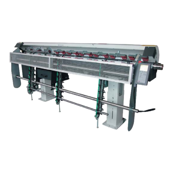
Common Issues he Hydrobar Sprint 555 is designed to be a user-friendly, simple, and reliable bar feeder, covering a range of diameters 0.250” to 2.000” (up to 2.125” with bar end preparation). Although easy to use, including extremely quick changeovers and the capability for unmanned operation this unit is not flawless. -
Page 60: Low Voltage / Plc Shutdown
Description: The Hydrobar Sprint 555 uses a SAIA PCD2 controller (PLC) to send/receive inputs/outputs. The PLC is powered by a +24VDC input supplied by a transformer. The input supply voltage must be regulated to ensure proper functioning. The remote control station, which is used to send/receive data back and forth with the PLC, is powered by the +24VDC on the PLC. -
Page 61: Cannot Change Application Setup Parameters
Press the “STOP” key on the remote control station and proceed with changing the parameters. Multiple Bars have been Loaded into the Channel Two bars loaded at a time Cause Solution Switch SQ9 is out of adjustment. Adjust switch SQ9. HYDROBAR SPRINT 555... -
Page 62: Rotating Sleeves
Description: The Hydrobar Sprint 555 is equipped with a rotating sleeve mounted on the front end of the pushing rod. The rotating sleeve is to ensure that the bar stock rotates with virtually zero friction during ideal running conditions. However, since there is no such thing as perfect running conditions, these parts will eventually wear down. -
Page 63: Collets
Description: The Hydrobar Sprint 555 bar feeder is equipped with a collet on the front of the pushing rod in which the bar stock is inserted mechanically during top-cut positioning. The collet grips the bar stock so that once the last piece has been cut off the remnant can be removed by the bar feeder, and for Swiss style machines so the pusher stays with the bar stock while the machine makes its Z-axis movements. -
Page 64: Front Rest Issues
Check the bar stock diameter and Front rest is not closing enough on the bar parameters. guiding channel size parameters. stock SQ13 switch is mis-adjusted or Check the functionality of the SQ14 defective. switch. Front rest is mis-calibrated. HYDROBAR SPRINT 555... -
Page 65: Vibration Issues
Vibration Issues The term “vibration” is being used regarding the Hydrobar Sprint 555, to indicate that the RPM performance of the lathe is physically deteriorated, to the point of creating an unbalanced rotational oscillation of the bar stock that is detrimental to the machining process. -
Page 67: Procedures
The video clips can be viewed on a PC with a compatible video card from the CD-ROM version of this manual. HYDROBAR SPRINT 555... -
Page 68: Front Rest Override
To override the front rest, press the F4 (PAGE DOWN) function key. The remote station should appear like the second figure below and is should say that it is enabled. Press and hold the “X” until the front rest becomes disabled, as shown in the third figure. HYDROBAR SPRINT 555... - Page 69 Note: After having completed Step 4, the front rest is no longer locked in the open position. The front rest is now enabled. Step 5: Press STOP to exit and return to the main menu. Procedure complete. HYDROBAR SPRINT 555...
-
Page 70: Reference Procedure
Step 3: Press the F1 button (reference icon) and the carrier flag will travel toward the home position. Once the flag has reached the home position (verified by switch SQ5-input I0.7), the reference sequence is complete. Procedure complete. HYDROBAR SPRINT 555... -
Page 71: Adjustment Procedure For End Of Bar
Press the MENU key on the display. Step 2: Press F4 (PAGE DOWN) until the PARAMETERS RELATED TO POSITIONING screen is displayed and press F3 (ENTER). Step 3: On the first screen displayed, END OF BAR POSITION, press F3 (SET). HYDROBAR SPRINT 555... - Page 72 Press and hold the F-key corresponding to the pusher forward icon until the pusher is ½” behind the main collet. Step 7: Once the desired position is reached, press and hold F3 (ENTER) to set the end of bar position. Step 8: Press F2 (ESC) to exit the menu. Procedure complete. HYDROBAR SPRINT 555...
-
Page 73: Top Cut Position Adjustment
Press F3 (ENTER) to enter into the Parameters Related to Positioning menu. Step 5: Press F4 (PAGE DOWN) until the Top Cut Position is displayed. Step 6: Press F3 (SET) to set or make changes to top cut position. HYDROBAR SPRINT 555... - Page 74 Enter the correction value with the numerical keys. Then press the F1 key (+) to add the value, or press the F4 key (-) to subtract it. The display will read the new top cut position. Step 9: To exit the top cut set mode, press F2 (ESC). By Teach In: Step 1: On a clear screen, press F1 (MANUAL MODE). HYDROBAR SPRINT 555...
- Page 75 Press F3 (ENTER) to enter into the Parameters Related to Positioning menu. Step 7: Press F4 (PAGE DOWN) until the Top Cut Position is displayed. Step 8: Press F3 (SET) to set or make changes to top cut position. HYDROBAR SPRINT 555...
- Page 76 The feeding pusher is now facing the bar. The moveable vise moves back and positions the material inside the collet of the bar feed system. Step 11: Press the F1 (FWD) key and advance the bar stock to the desired position. HYDROBAR SPRINT 555...
- Page 77 Chapter 3: Procedures 3 - 1 1 Step 12: To validate the new top cut position, keep F3 (ENTER) pressed until the ENTER icon disappears. Step 13: To exit the set mode, press the STOP key. Procedure complete. HYDROBAR SPRINT 555...
- Page 79 Smart Media. Smart Media, which is mainly used in photography, has been integrated for use with the user-friendly remote control station. The Smart Media Card holds a backup program for the Hydrobar Sprint 555 if at anytime there has been a power failure or any error has occurred in the user program. In addition, it automatically backs up any application/interface parameters that have been set for the most recent application being ran.
- Page 80 Remove the 9 screws on the back of the pendant, and then carefully separate the back half from the front half. Step 4: Once the 2 halves are separated insert the Smart Media card (solid back side facing up and chamfered edge away from you) into the slot. Black side Chamfered edge facing up away from you HYDROBAR SPRINT 555...
-
Page 81: Software Update/Restore
A password is required at this point using the number buttons on the pendant enter 3; 1; 4; 1; 5. Step 9: There are 4 menu choices on this screen, press the F3 key for PLC Fault. HYDROBAR SPRINT 555... - Page 82 Step 12: Press F4 (OK). Step 13: Turn off power to bar feeder Step 14: Move the RUN/STOP switch to RUN position. Step 15: Restore power to the bar feeder. Procedure complete. HYDROBAR SPRINT 555...
-
Page 83: Software Update - V2.08
Remove the 9 screws on the back of the pendant, and then carefully separate the back half from the front half. Step 4: Once the 2 halves are separated insert the Smart Media card (solid back side facing up and chamfered edge away from you) into the slot. Black side Chamfered edge facing up away from you HYDROBAR SPRINT 555... - Page 84 A password is required at this point using the number buttons on the pendant enter 3; 1; 4; 1; 5. Step 9: There are 4 menu choices on this screen, press the F2 key for Software Update. HYDROBAR SPRINT 555...
- Page 85 Step 12: Press F4 (OK). Step 13: Turn off power to bar feeder Step 14: Move the RUN/STOP switch to RUN position. Step 15: Restore power to the bar feeder. Procedure complete. HYDROBAR SPRINT 555...
-
Page 87: Chapter 5
Maintenance eriodic maintenance of the Hydrobar Sprint 555 bar feeding system can only serve to improve the operation and prolong its useful life. Following a few simple steps can be extremely helpful and takes relatively no time at all. The list of... -
Page 88: Daily Maintenance
This is a wear item and it is recommended to keep spares on hand, refer to Recommended Spare Parts List pg. 6-2. Drive belt Over time, it is possible that the tension of the drive belt may loosen up. To tighten the belt, refer to Belt Tension Adjustment. HYDROBAR SPRINT 555... -
Page 89: Annual Maintenance
0% off 100% on 5 years 4 years 30% off 70% on 4 years 1 year Verify the alignment of the bar feeder Check alignment of bar feeder to lathe spindle to make sure neither have shifted. HYDROBAR SPRINT 555... -
Page 91: Chapter 6
Note: When ordering parts the following information will be needed to ensure better customer support: • Bar feeder type • Bar feeder Serial Number (found on the hydraulic tank next to the air regulator) • Bar stock diameter • Lathe type (make and model) HYDROBAR SPRINT 555... -
Page 92: Recommended Spare Parts List
6-5 Parts Order Form) Spindle Liners Ensure that the properly sized spindle liner has been installed (.030” -.060” over bar stock size). Ensure the liner is straight (check total run out), and has all o-rings intact. HYDROBAR SPRINT 555... -
Page 93: Guiding Channel Performance Chart (W/O Remnant Retraction)
Chapter 6: Spare Parts 6 - 3 Guiding Channel Performance Chart (w/o remnant retraction) HYDROBAR SPRINT 555... -
Page 94: Guiding Channel Performance Chart (With Remnant Retraction)
6 - 4 Chapter 6: Spare Parts Guiding Channel Performance Chart (with remnant retraction) HYDROBAR SPRINT 555... -
Page 95: Parts Order Form
Serial # of Bar feeder: Model of Lathe: Bar stock diameter: Qty. Part # Description Note: To place an order, this form should be photocopied, completed and faxed to (513) 528-8320 Please call (513) 528-5674 or price and availability of parts. HYDROBAR SPRINT 555... -
Page 96: Electrical Box Components
Bar feed alarm relay 4.606 M-code finish/ Load complete relay 4.606 End of bar relay 4.606 Spindle interlock relay 4.606 Auxiliary end of bar relay 4.769 Transformer w/ 230VAC output power supply 4.779 24 VDC Power supply 150W HYDROBAR SPRINT 555... -
Page 97: Upper Guiding Channel Support (Double Support)
Chapter 6: Spare Parts 6 - 7 Upper Guiding Channel Support (double support) HYDROBAR SPRINT 555... -
Page 98: Lower Guiding Channel Support (Double Support)
6 - 8 Chapter 6: Spare Parts Lower Guiding Channel Support (double support) HYDROBAR SPRINT 555... -
Page 99: Lower Guiding Channel Support (Single Support)
Chapter 6: Spare Parts 6 - 9 Lower Guiding Channel Support (single support) HYDROBAR SPRINT 555... -
Page 100: Upper Guiding Channel Support (Single Support W/ Pusher Locking Tabs)
6 -10 Chapter 6: Spare Parts Upper Guiding Channel Support (single support w/ pusher locking tabs) HYDROBAR SPRINT 555... -
Page 101: Upper Guiding Channel Support (Single Support)
Chapter 6: Spare Parts 6 - 11 Upper Guiding Channel Support (single support) HYDROBAR SPRINT 555... -
Page 102: Guiding Channel Locking Mechanism (L/F)
6 -12 Chapter 6: Spare Parts Guiding Channel Locking Mechanism (L/F) HYDROBAR SPRINT 555... -
Page 103: Upper Guiding Channel Locking Paw
Chapter 6: Spare Parts 6 - 13 Upper Guiding Channel Locking Paw HYDROBAR SPRINT 555... -
Page 104: Guiding Channel Actuator Shaft (L/F)
6 -14 Chapter 6: Spare Parts Guiding Channel Actuator Shaft (L/F) HYDROBAR SPRINT 555... -
Page 105: Guiding Channel Actuating Cylinder
Chapter 6: Spare Parts 6 - 15 Guiding Channel Actuating Cylinder HYDROBAR SPRINT 555... -
Page 106: Guiding Channel Actuator Shaft (R/F)
6 -16 Chapter 6: Spare Parts Guiding Channel Actuator Shaft (R/F) HYDROBAR SPRINT 555... -
Page 107: Cam Locking Mechanism Drive Motor
Chapter 6: Spare Parts 6 - 17 Cam Locking Mechanism Drive Motor HYDROBAR SPRINT 555... -
Page 108: Outboard Support Sub-Assembly
6 -18 Chapter 6: Spare Parts Outboard Support Sub-Assembly HYDROBAR SPRINT 555... -
Page 109: Chain Magazine Rack
Chapter 6: Spare Parts 6 - 19 Chain Magazine Rack HYDROBAR SPRINT 555... -
Page 110: Pusher Locking Mechanism Sub-Assembly
6 -20 Chapter 6: Spare Parts Pusher Locking Mechanism Sub-Assembly HYDROBAR SPRINT 555... -
Page 111: Belt Drive Sub-Assembly
Chapter 6: Spare Parts 6 - 21 Belt Drive Sub-Assembly HYDROBAR SPRINT 555...
Need help?
Do you have a question about the HYDROBAR SPRINT 555 and is the answer not in the manual?
Questions and answers