Table of Contents
Advertisement
Quick Links
Advertisement
Table of Contents

Subscribe to Our Youtube Channel
Related Manuals for Vivo STAND-SIT1WD


Summary of Contents for Vivo STAND-SIT1WD
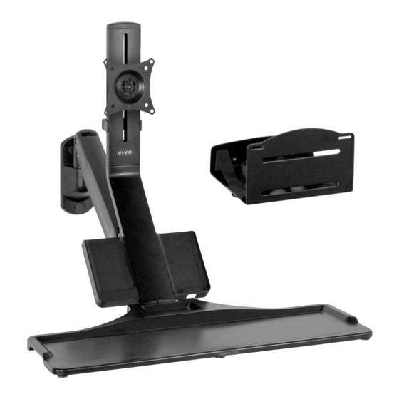
- Page 1 Sit to Stand Single Monitor Wall Mount Workstation Instruction Manual SKU: STAND-SIT1WD Scan the QR code with your mobile device or follow the link for helpful videos and specifications related to this product. https://vivo-us.com/products/stand-sit1wd help@vivo-us.com www.vivo-us.com 309-278-5303...
- Page 2 CAUTION! DO NOT INSTALL INTO DRYWALL ALONE. VERIFY YOUR WALL CONSTRUCTION. USE WOOD STUDS TO MOUNT. We include mounting for brick and concrete walls. If unsure, please contact us at vivo-us. com, email at help@vivo-us.com, or call us at 309-278-5303.
- Page 3 TOOLS NEEDED DO NOT EXCEED WEIGHT CAPACITY. 2.2 - 19.8lbs Failure to do so may result in serious injury. (1 - 9kg) Phillips Drill Screwdriver Pencil ASSEMBLY STEPS STEP 1 OPTION A: Wood Stud Mounting OPTION B: Concrete Wall Mounting Using vertical holes in wall bracket (A) as a guide, Using horizontal and lower holes in wall bracket (A) as a guide, mark drilling locations on wall.
- Page 4 STEP 4 Remove the knob from the lower support arm (E) to separate into lower support arm (E1) and knob (E2). STEP 5 Assemble smartphone tray (C) to lower support arm using M5x10 screws (M) with a Phillips screwdriver. STEP 6 Assemble keyboard tray (D) to lower support arm using ST4.8x16 screws (L) with a Phillips screwdriver.
- Page 5 STEP 8 Place the support arm/tray assembly onto the upper post of the adjustable arm, then secure using the 3mm Allen wrench (N). STEP 9 Adjust keyboard tray tilt using the 4mm Allen wrench (O). Turn the adjustment screw clockwise to tilt up to position 1a, and counter-clockwise to tilt down to position 1b.
- Page 6 STEP 11 Place the monitor with VESA plate into the bracket on the upper support arm, then turn the screw on the bracket to secure the monitor. STEP 12 Loosen knob in back to adjust monitor height. To adjust gas spring support, turn the hex screw on top of the rear joint using the 6mm Allen wrench.
- Page 7 STEP 13 Install cable clip (H) to back of upper support arm and remove cable cover from adjustable arm (B). STEP 14 Organize cables and reinstall cable cover to adjustable arm. Adjust as Desired 10° +/-10° 180° 90° 90°...
- Page 8 - 83% within < 2hr - 92% within < 3hr www.vivo-us.com : < 15 M AVG. RESOLUTION TIME (within office hrs) : 5M 4S 309-278-5303 AVG. RESOLUTION TIME (within office hrs) FOR MORE VIVO PRODUCTS, CHECK OUT OUR WEBSITE AT: www.vivo-us.com...
Need help?
Do you have a question about the STAND-SIT1WD and is the answer not in the manual?
Questions and answers