Table of Contents
Advertisement
Quick Links
Instruction Manual Book
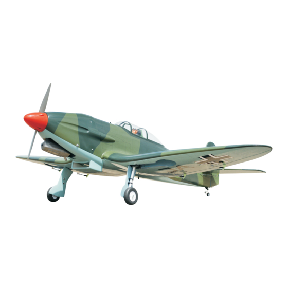
HEINKEL HE-112B
95% ALMOST READY TO FLY
SPECIFICATION:
- Wingspan: 1,550mm (61.02in).
- Length: 1,560mm (61.42in).
- Weight: 4.5kg (9.9lbs).
- Wing area: 49.0 dm .
- Wing loading: 91.8 g/dm .
- Servo mount: 42mm x 21mm.
- Wing type: Naca Airfoil.
- Spinner: 80mm.
- Gear type: Electric retract gear,
size: (92.2 x 51 x 30.6)mm (not included).
Oleo struts (included).
NOT INCLUDING ELECTRIC RETRACT GEAR.
ONLY INCLUDING OLEO STRUTS.
ALL BALSA - PLY WOOD CONSTRUCTION.
COVERED IN A HEAT-SHRINK FILM WITH PRINTED.
2
2
Item code: BH159.
Parts listing required (not included):
- Radio: 06 channels.
- Servo: 07 - 08 servos.
- Engine: 61 - 91 ; 15 cc Gas.
- Motor: Brushless outrunner 1200-2200W, 650KV.
- Propeller: Suit with your engine.
Recommended Motor
and Battery set up (not included):
- Motor: RIMFIRE.60.
- Lipo cell: 6 cells 4,000-5,000mAh.
- Receiver battery: 6V/ 1200-2000mAh NiMH.
- ESC: 80A.
Made in Vietnam.
Advertisement
Table of Contents

Related Manuals for Black Horse Model HEINKEL HE-112B


Summary of Contents for Black Horse Model HEINKEL HE-112B
- Page 1 Instruction Manual Book Item code: BH159. HEINKEL HE-112B NOT INCLUDING ELECTRIC RETRACT GEAR. ONLY INCLUDING OLEO STRUTS. ALL BALSA - PLY WOOD CONSTRUCTION. COVERED IN A HEAT-SHRINK FILM WITH PRINTED. 95% ALMOST READY TO FLY SPECIFICATION: - Wingspan: 1,550mm (61.02in).
- Page 2 Item code: BH159 This instruction manual is designed to help you build a great flying aeroplane. Please read this manual thoroughly before starting assembly of your HEINKEL HE-112B. Use the parts listing below to identify all parts. WARNING Please be aware that this aeroplane is not a toy and if assembled or used incorrectly it is capable of causing injury to people or property.
-
Page 3: Tools And Supplies Needed
HEINKEL HE-112B Item code: BH159 TOOLS & SUPPLIES NEEDED EPOXY A EPOXY B Epoxy Glue (5 minute type). Hand or electric drill. Epoxy Glue (30 minute type). Threadlocker (screw cement). Hobby knife. Some more tools. Awl. Assorted drill bits. Phillips head screwdriver. - Page 4 HEINKEL HE-112B Item code: BH159 : Fuselage. : Wing panel ( 2a, 2b . : Horizontal stabilizer. : Rudder. : Aluminium wing dihedral brace. : Cowling. : Spinner. : Cockpit fuselage (8a : Canopy, 8b : Pilot, c : Top hatch fuselage.).
- Page 5 HEINKEL HE-112B Item code: BH159 * Apply drops of thin CA to the top and bottom of each 1. INSTALLING THE AILERONS, FLAPS hinge. Do not use CA accelerator. After the CA has fully hardened, test the hinges by pulling on the aileron.
-
Page 6: Installing Main Gear
HEINKEL HE-112B Item code: BH159 3. INSTALLING THE CONTROL HORNS, LINKAGES 5mm Silicone Tube Flaslink - - - - - 4 - - - 4 Flaslink 2mm Nut - - 4 Silicone Tube Horn Servo arm - - - - -... -
Page 7: Option 2: Electric Gear Retracts
HEINKEL HE-112B Item code: BH159 5mm Collar Secure 5x35mm Apply threadlocker 3x15mm C/A glue Secure OPTION 2: ELECTRIC GEAR RETRACTS Electric not included. 92.20 24.10 48.50 21.00 43.70 30.70 5. INSTALLING THE ENGINE MOUNT There are two options: 1. Electric motor 2. -
Page 8: Installing The Stopper Assembly
HEINKEL HE-112B Item code: BH159 4) Carefully bend the third nylon tube down at a 45 degree angle (using a cigarette lighter). This tube will be vent tube to the fueling valve. When the stopper assembly is installed in the tank, the top of the vent tube should rest just below the top surface of the tank. -
Page 9: Installing The Throttle Pushrod
HEINKEL HE-112B Item code: BH159 125mm * Locate the long piece of wire used for the throttle pushrod. One end of the wire has been pre-bend in to a "Z" bend at the factory. This "Z" bend should be inserted into the throttle arm of the engine when the engine is fitted onto the engine mount. -
Page 10: Installing Horizontal Stabilizer
HEINKEL HE-112B Item code: BH159 Drill two holes 2.5mm and secure 3x12mm. Cowl area cutout for engine head Also as the same procedure for the left side. 8. INSTALLING HORIZONTAL STABILIZER Make sure the horizontal stabilizer is square and centered to the fuselage by taking measurements, but 1) Elevator install as same as the way of aileron. -
Page 11: Elevator Control Horn Installation
HEINKEL HE-112B Item code: BH159 Top side and bottom side 8.1. ELEVATOR CONTROL HORN C/A glue INSTALLATION 5mm Silicone Tube - - - - - 2 - - - 2 Flaslink Horn Silicone Tube - - - - 2 - - - - -... -
Page 12: Rudder Pushrod Installation
HEINKEL HE-112B Item code: BH159 9. RUDDER INSTALLATION RUDDER PUSHROD INSTALLATION Rudder install as same as the way of aileron. Rudder pushrod install as same as the way of elevator pushrod. Please see pictures below. Rudder Rudder pushrod Rudder control horn... -
Page 13: Installing The Switch, Receiver And Battery
HEINKEL HE-112B Item code: BH159 Drill a hole 1. Push in 2.5mm 2. A+B Epoxy glue 2) Mark the locations of the two mounting screws. Remove the tail wheel bracket and drill 2.5mm pilot holes at the locations marked. 3x12mm... -
Page 14: Wing Attachment
HEINKEL HE-112B Item code: BH159 Insert the wing panel as pictures below. 12. WING ATTACHMENT Locate the aluminium wing dihedral brace. 19mm Aluminium tube. 545mm *** Test fit the aluminium tube dihedral brace into each wing haft. The brace should slide in easily. If not, use 220 grit sand around the edges and ends of the brace until it fits properly. -
Page 15: Control Throws
HEINKEL HE-112B Item code: BH159 BALANCING 1) It is critical that your airplane be balanced correctly. Improper balance will cause your plane to lose control 111 mm and crash. THE CENTER OF GRAVITY IS LOCATED 111MM BACK FROM THE LEADING EDGE OF THE WING. -
Page 16: Pre-Flight Check
HEINKEL HE-112B Item code: BH159 12mm 12mm Aileron control 25mm Flap control 12mm 12mm Elevator control 25mm 25mm Rudder control PRE-FLIGHT CHECK 1) Completely charge your transmitter and receiver batteries before your first day of flying. 2) Check every bolt and every glue joint in your plane to ensure that everything is tight and well bonded. - Page 17 I/C FLINGT WARNINGS Always operate in open areas, away from NEVER fly near power lines,aerials or ALWAYS adjust the engine from behind factories, hospitals, schools, buildings the propeller, and do not allow any part of other dangerous areas including airports, and houses etc.
Need help?
Do you have a question about the HEINKEL HE-112B and is the answer not in the manual?
Questions and answers