Table of Contents
Advertisement
Quick Links
Advertisement
Table of Contents

Related Manuals for Target warwick FKWWLBCBBR


Summary of Contents for Target warwick FKWWLBCBBR
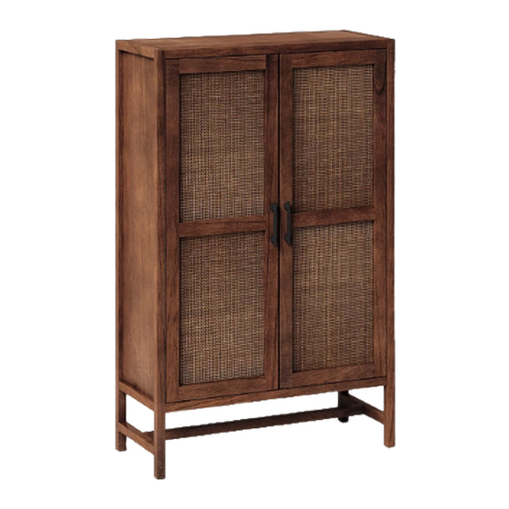
- Page 1 warwick library cabinet style # FKWWLBCBBR (fawn brown) dpci # 249-17-0827 tcin # 53536786 style # FKWWLBCBWH (white) dpci # 249-17-3054 tcin # 54187402 style # FKWWLBCBBK (jet black) dpci # 249-17-6416 tcin # 78054342 >> assembly instructions...
- Page 2 Congratulations on your latest Target purchase. Now what? Don’t start sweating over this box of parts. This will be easy. We did the hard work for you. All you need to do is follow our simple instructions and you’ll be on your way to transforming your room in no time.
- Page 3 table of contents introduction hardware parts list assembly 7-13 QUESTIONS? Just call 1-855-MYTGTHOME (855-698-4846) for parts and service. For faster service, have the style number and dpci number ready when calling.
-
Page 4: Table Of Contents
hardware (H1) x 12 (H2) x 8 (H3) x 8 (H4) x 23 (H5) x 4 dowel bolt lock washer pan head screw handle bolt (H6) x 2 (H7) x 8 (H8) x 2 (H9) x 1 (H10) x 6 handle shelf pin long flat head screw... - Page 5 hardware (H11) x 24 (H12) x 1 (H13) x 1 (H14) x 1 (H15) x 1 short flat head screw wall anchor wall screw truss head screw wall strap (H16) x 10 washer...
- Page 6 exploded diagram ITEM DESCRIPTION QUANTITY top panel left side panel right side panel bottom panel adjustable shelf back panel door stretcher...
-
Page 7: (H1) X 12
step 1: attach top panel, bottom panel, and bottom rail to side panels (H1) x 12 (H2) x 8 dowel bolt (H3) x 8 (H16) x 8 (H9) x 1 lock washer washer allen wrench 1.1. Carefully small wooden dowels into place in top panel, bottom panel, and bottom rail. Leave 1/2” of the dowels sticking out. 1.2. -
Page 8: (H8) X 2
step 2: secure bottom rail front (H8) x 2 long flat head screw 2.1. Do not over tighten screws. -
Page 9: (H4) X 23
step 3: attach back panel FAILURE TO FOLLOW ALL DIRECTIONS ON THIS PAGE MAY RESULT IN UNEVEN DOOR ALIGNMENT Begin by installing all of the screws along one edge of the back panel. Next, using a square or tape measure, make sure that the cabinet is square. - Page 10 step 4: install adjustable shelf finished edge (H7) x 8 finished edge shelf support 4.1. Insert shelf supports into desired hole. Different holes accommodate different shelf heights. 4.2. Angle shelf to fit between the rails and set on top of shelf supports.
-
Page 11: (H9) X
step 5. install door hinges (H10) x 6 (H11) x 12 hinge short flat head screw 5.1. Do not over tighten screws. -
Page 12: (H5) X 4
step 6: attach doors to cabinet (H5) x 4 (H6) x 2 (H11) x 12 handle bolt handle short flat head screw 6.1. Align small flat head screws with pre-drilled holes to attach hinge to door. Do not over tighten screws. 6.2. - Page 13 step 7: install anti-tip kit (H15) (H12) Position against wall Mark position of strap hole on wall Mark position of strap hole on wall Drill 1/4” hole (H14) (H16) Tap in wall anchor adjustable leg levelers (H16) (H13) Fasten anti-tip strap with wall screw Fasten anti-tip strap with wall screw provided provided...
- Page 14 e l f l b s 1. This unit has been designed for the weight shown. Exceeding this recommended weight could result in excessive “sagging” of the top. Extreme overloading can cause failure of the top and possible injury. 2. Furniture Care Instructions: Dust with a clean, lint-free cloth. Use a spray furniture polish as needed. QUESTIONS? Just call 1-855-MYTGTHOME (855-698-4846) for parts and service.
- Page 15 SALICE SALICE 600 Series Adjustment Instructions 600 Series Adjustment Instructions Height Adjustment is achieved by loosening the two screws indicated by the arrows. Once all plates are loosened, the door can be repositioned vertically. The screws are then tightened when the door is in the desired position. Depth Adjustment is achieved by loosening the center screw indicated by the arrow.
- Page 16 SALICE LIFETIME GUARANTEE AND LIMITED WARRANTY* Salice America, Inc., warrants that all hinges and/or Salice products contained in Quality That Lasts A Lifetime this product, (but not the product itself) against defects in material and workman- ship for as long as the original consumer purchaser owns the products. Salice will send the original consumer purchaser a new Salice hinge to replace any defective Salice hinge subject to this warranty without charge.
- Page 17 © 2019 Target. The Bullseye Design is a trademark of Target Brands, Inc. All rights reserved.
Need help?
Do you have a question about the warwick FKWWLBCBBR and is the answer not in the manual?
Questions and answers