Advertisement
Quick Links
SELECTRONIC
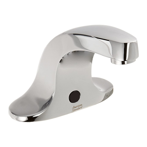
Innsbrook Lavatory Proximity Faucet
Certi ed to comply with:
• ASME A112.18.1
NOTE TO INSTALLER: Please give this manual to the customer after installation.
To learn more about American Standard Selectronic
or e-mail us at: CRTTEAM@lixilamericas.com
For Parts, Service, Warranty or other Assistance,
please call (844) CRT-TEAM / (844) 278-8326 (In Canada: 1-800-387-0369)
© 2019 AS America Inc.
®
Products visit our website at: www.americanstandard-us.com
®
(In Toronto Area only: 1-905-306-1093)
1
MODEL NUMBERS
CAUTION: Use only American Standard
supplied cable sets. Using non-AS supplied
cables, or cutting, splicing or modifying any
components will void the warranty.
Product No.'s & Options
Speci cations
Faucet Installation
Electrical Installation
Start-up / Maintenance
FAQ's / Troubleshooting
Parts
605X.202
605X.204
605X.205
1
2
2-3
4-6
7-8
9-10
11
M965652 Rev. 1.9 (3/19)
Advertisement

Related Manuals for American Standard Innsbrook SELECTRONIC 605 202 Series


Summary of Contents for American Standard Innsbrook SELECTRONIC 605 202 Series
- Page 1 Parts Certi ed to comply with: • ASME A112.18.1 NOTE TO INSTALLER: Please give this manual to the customer after installation. To learn more about American Standard Selectronic Products visit our website at: www.americanstandard-us.com ® or e-mail us at: CRTTEAM@lixilamericas.com...
- Page 2 Thank you for selecting American-Standard...the benchmark of ne quality for over 100 years. To ensure that your installation proceeds smoothly--please read these instructions carefully before you begin. All American Standard Products Are Water Tested At Our Factory. UNPACKING Some Residual Water May Remain In The Valve During Shipping The illustration below shows the tting and all loose items after they have been removed from the carton.
-
Page 3: Faucet Installation
35mm 38mm regulations and standards. (1-3/8) (1-1/2) DIA. MAX. 3 HOLES CAUTION: Use only American Standard supplied 57mm 102mm (2-1/4) transformers and cable sets. Using non-AS supplied 125mm (4-7/8) cables, or cutting, splicing or modifying any components will void the warranty. - Page 4 MOUNT CONTROL BOX; Fig. 2 Fig. 2 LAVATORY RIM OR MOUNTING SURFACE 1. Determine location of CONTROL BOX (1). It must be located with-in the 14" (356mm) by 21" (533mm) shaded area shown in Figure 2 in order for electrical connections from the spout 14"...
-
Page 5: Electrical Installation
6. Reinstall CONTROL BOX COVER (1). Tighten cover screws rmly. STANDARD BATTERY CAUTION: Use only American Standard supplied cable sets. PWRX Using non-AS supplied cables, or cutting, splicing or modifying any components will void the warranty. M965652 Rev. 1.9 (3/19) - Page 6 6b. Connect the10' EXTENSION (10b) to the POWER Fig. 2c SUPPLY CABLE (15). Fig. 2c. 10' EXTENSION CAUTION: Use only American Standard supplied cable sets. Using non-AS supplied cables, or cutting, splicing or modifying any components will void the warranty. BLACK & WHITE...
- Page 7 Max. of 15 Units on one AC POWER SUPPLY. 7. Reinstall CONTROL BOX COVERS. Tighten cover screws rmly. CAUTION: Use only American Standard supplied cable sets. Using non-AS supplied cables, or cutting, splicing or modifying any components will void the warranty. M965652 Rev. 1.9 (3/19)
-
Page 8: Maintenance
Fig 1 MAINTENANCE T I O N D E T E C Z O N E HAND WASH SENSOR OPERATION; Fig. 1 When the Sensor detects a user, the water immediately starts to flow. Water flow will stop 2 seconds after user is out of sensor range. - Page 9 INSTALL / REPLACE THE BATTERY Fig. 4 or PWRX; Fig. 4 STANDARD 1. Remove COVER from CONTROL BOX (1). BATTERY 2. Disconnect BATTERY HOLDER (3) from CABLE (5). 3. Remove old BATTERY from Battery Holder (3). Install new BATTERY (2) making sure the terminal side is inserted rst and shape of the battery follows the shape of the BATTERY HOLDER (3).
- Page 10 GENERAL CLEANING; Fig. 5 1. For general cleaning use a damp, soft cloth to clean the spout and the sensor. Fig.6 2. For cleaning dirt use a soft cloth with diluted dish washing detergent. Wipe the area using a wet cloth and dry using a soft cloth.
-
Page 11: Troubleshooting Flowcharts
P ro d u c t n a m e s l is t e d h e re i n a re t r a d e m a r k s o f A S A m e r i c a , I nc . ©2 01 9 To learn more about American Standard Selectronic Products visit our website at: ®...
Need help?
Do you have a question about the Innsbrook SELECTRONIC 605 202 Series and is the answer not in the manual?
Questions and answers