Advertisement
Quick Links
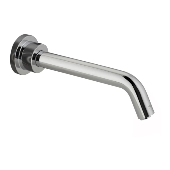
SERIN™
Wall Mount Electronic
Proximity Lavatory Faucet
NOTE: Please refer to R350 Mounting Kit
installation instructions #M965614 prior to
faucet installation.
Certified to comply with ASME A112.18.1
© 2014 American Standard
M 9 6 5 6 13
NOTE TO INSTALLER: Please give this manual to the customer after installation.
To learn more about American Standard Faucets visit our website at:
www.americanstandard.com or U.S. customer's e-mail us at: sensor@americanstandard.com
For Parts, Service, Warranty or other Assistance,
(855) 752-9259 (In Canada: 1-800-387-0369)
please call
Product No.'s & Options
Specifications
Faucet Installation
Electrical Installation
Start-up / Maintenance
FAQ's / Troubleshooting
Replacement Parts
(In Toronto Area only: 1-905-3061093)
(In Toronto Area only: 1-905-3061093)
MODEL NUMBERS
T064.342
T064.353
T064.362
T064.372
T064.392
CAUTION: Use only American Standard
supplied cable sets. Using non-AS supplied
cables, or cutting, splicing or modifying any
components will void the warranty.
T064.345
T064.355
T064.365
T064.375
T064.395
1
2
2-5
6-8
9-10
10-11
12
Advertisement

Subscribe to Our Youtube Channel
Related Manuals for American Standard SERIN T064.342


Summary of Contents for American Standard SERIN T064.342
- Page 1 M 9 6 5 6 13 NOTE TO INSTALLER: Please give this manual to the customer after installation. To learn more about American Standard Faucets visit our website at: www.americanstandard.com or U.S. customer's e-mail us at: sensor@americanstandard.com For Parts, Service, Warranty or other Assistance,...
- Page 2 M 9 6 5 6 12 NOTE TO INSTALLER: Please give this manual to the customer after installation. To learn more about American Standard Faucets visit our website at: www.us.amstd.com or U.S. customer's e-mail us at: sensor@americanstandard.com For Parts, Service, Warranty or other Assistance,...
-
Page 3: Faucet Installation
(4" - 8" Recommended) MIN. (5-7/8) - MAX. 8-7/8 regulations and standards. 29-1/2" MAX. (750mm) CAUTION: Use only American Standard 81mm (3-3/16) supplied cable sets. Using non-AS supplied cables, or cutting, splicing or modifying any components will void the warranty. - Page 4 INSTALL SPOUT MOUNTING KIT; Fig. 2 Fig. 2 1. Make sure that SEAL (7) is installed into the groove on the back of the MOUNTING FLANGE (8). Feed the CORD HOLDER (3a) and the EXTENSION CABLES (5a) through the MOUNTING FLANGE (8). 2.
- Page 5 ALIGN SPOUT ASSEMBLY; Fig. 5 Fig. 5 SPOUT LENGTH 150mm - 225mm 1. Align and push SPOUT (12) through hole, loosely MIN. (5-7/8) - MAX. 8-7/8 installed MOUNTING FLANGE (8) and MOUNTING PLATE (10). 2. Once MOUNTING FLANGE (8) is aligned with MOUNTING PLATE (10) opening, tighten the three MOUNTING FLANGE SCREWS (9).
- Page 6 INSTALL SUPPLY ELBOW Fig. 7 ASSEMBLY & ENCLOSURE; Fig. 7 and Fig. 7a 1. Install HOSE CLAMP (22) onto SPOUT HOSE (15). Install SPOUT HOSE (15) onto ELBOW NIPPLE (23). Fully tighten HOSE CLAMP (22) to secure SPOUT HOSE (15) to ELBOW ASSEMBLY (24). Fig. 7. 2.
-
Page 7: Electrical Installation
POWER PACK Fig. 1d. 6. Replace ENCLOSURE COVER (1). Tighten cover screws firmly. CAUTION: Use only American Standard supplied cable sets. Using non-AS supplied cables, or cutting, splicing or modifying any components will void the warranty. M 9 6 5 6 13... - Page 8 9. Connect the 10 ft. EXTENSION (11b) to the POWER SUPPLY CABLE (16). Mount POWER SUPPLY (12) into ELECTRICAL BOX (14). Fig. 3a CAUTION: Use only American Standard 4" ELECTRICAL BOX OR EQUIVALENT BY supplied cable sets. Using non-AS supplied...
- Page 9 Unit #1 Unit #2 Unit #3 Fig. 4 10 ft. EXTENSION 10 ft. EXTENSION CABLE CABLE *MAXIMUM OF 15 UNITS PER AC POWER SUPPLY. 10' MAXIMUM CABLE LENGTH BETWEEN UNITS. AC POWER YOU CAN USE EITHER THE PLUG-IN SUPPLY OR HARD-WIRED TRANSFORMER. 4"...
-
Page 10: Start-Up / Maintenance
START-UP / MAINTENANCE Fig. 1 HAND WASH SENSOR OPERATION; Fig. 1 Prior to making power connection, make sure detection zone is not obstructed. Sensor is self adjusting. Keep detection zone clear for 15 seconds after power is connected. When the Sensor detects a user, the water immediately starts to flow. - Page 11 Fig. 4 HOW TO CLEAN AND REMOVE THE AERATOR OR SPRAY; Fig. 4 1. Remove AERATOR or SPRAY HOUSING (7) with KEY supplied with faucet. 2. Remove AERATOR or SPRAY (8) from HOUSING (7). 3. Clean the AERATOR or SPRAY SCREEN (9). 4.
-
Page 12: Troubleshooting Flowcharts
TROUBLESHOOTING FLOW CHARTS UNIT DOES NOT FUNCTION ARE EXTERNAL SUPPLY OPEN EXTERNAL SUPPLY STOPS. STOPS OPEN? IS INTERNAL SUPPLY OPEN INTERNAL SUPPLY STOP. STOP OPEN? (HEX KEY NEEDED) REPEATED DOUBLE FLASH CRITICALLY LOW BATTERY. ON SENSOR? INSTALL NEW BATTERY. DEAD BATTERY. INSTALL RECONNECT BATTERY TO SENSOR.
Need help?
Do you have a question about the SERIN T064.342 and is the answer not in the manual?
Questions and answers