
Related Manuals for ADTRAN HDSL DDM+ HTU-C


Summary of Contents for ADTRAN HDSL DDM+ HTU-C
- Page 1 ® HDSL DDM+ Transceiver Unit for Central Office Installation and Maintenance Practice Document Number: 61247003L6-5A CLEI: T1I3AANA_ _ April 2008...
- Page 2 In no event will ADTRAN be liable for any special, incidental, or consequential damages or for commercial losses even if ADTRAN has been advised thereof as a result of issue of this document.
- Page 3 Revision History Revision Date Description April 2008 Initial release Conventions The following typographical conventions are used in this document: This font indicates a cross-reference link. indicates screen menus, fields, and parameters. This font indicates keyboard keys ( ). Keys that are to be pressed simultaneously HIS FONT NTER are shown with a plus sign (...
- Page 4 HDSL DDM+ Transceiver Unit for Central Office Installation and Maintenance Practice Training ADTRAN offers training courses on our products. These courses include overviews on product features and functions while covering applications of ADTRAN product lines. ADTRAN provides a variety of training options, including customized training and courses taught at our facilities or at customer sites.
-
Page 5: Table Of Contents
Contents Introduction ................1 Description . - Page 6 ADTRAN Technical Support ........
- Page 7 ADTRAN Noise Margin Guidelines ........
- Page 8 ADTRAN Mode 11-Bit Codes ........
-
Page 9: Introduction
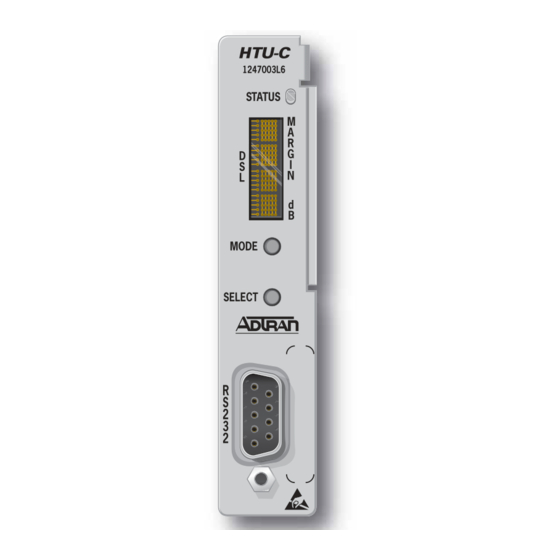
HDSL DDM+ Transceiver Unit for Central Office INTRODUCTION This practice is an installation and maintenance guide for the ADTRAN ® HDSL DDM+ Transceiver Unit for Central Office (DDM+ HTU-C). The DDM+ HTU-C (P/N 1247003L6) front panel is illus- trated in Figure Figure 1. -
Page 10: Description
DSX-1 signals are provided to and from the network while 2B1Q HDSL signals are provided to the local loop. The DDM+ HTU-C works in conjunction with the ADTRAN HDSL Transceiver Unit for the Remote end (HTU-R) and HDSL Range Extender (HRE) to provide a DS1 service up to 36,000 feet on the local loop. -
Page 11: Compliance
1. This device may not cause harmful interference 2. This device must accept any interference received, including interference that may cause undesired operation. Changes or modifications not expressly approved by ADTRAN could void the user’s authority to operate this equipment. Table 2 shows the compliance codes for the DDM+ HTU-C. - Page 12 HDSL DDM+ Transceiver Unit for Central Office Installation and Maintenance Practice CAUTION Per GR-1089-CORE Section 9, the DDM+ HTU-C does not have an internal DC connection between battery return and frame ground. As such, it may be installed in a DC-I (isolated) or DC-C (common) installation.
-
Page 13: Hdsl Deployment Guidelines
HDSL Deployment Guidelines HDSL DEPLOYMENT GUIDELINES The ADTRAN HDSL system is designed to provide DS1 based services over loops designed to comply with carrier service area (CSA) guidelines. CSA deployment guidelines are given below. • All loops are non-loaded only. -
Page 14: Table 3. Hdsl Loss Values
HDSL DDM+ Transceiver Unit for Central Office Installation and Maintenance Practice Table 3. HDSL Loss Values (200 kHz cable loss in dB/kft at 135 Ω ) Temperature Cable Gauge Cable Type 68° 90° 120° 3.902 4.051 4.253 Pulp 4.030 4.179 4.381 2.863 2.957... -
Page 15: Installation
After unpacking the DDM+ HTU-C, inspect it for damage. If damage has occurred, file a claim with the carrier then contact ADTRAN Customer Service. Refer to “Appendix C, Warranty” further information. If possible, keep the original shipping container for returning the DDM+ HTU-C for repair or for verification of shipping damage. -
Page 16: Instructions For Installing The Ddm+ Htu-C
HDSL DDM+ Transceiver Unit for Central Office Installation and Maintenance Practice Instructions for Installing the DDM+ HTU-C To install the DDM+ HTU-C, perform the following steps: 1. Hold the DDM+ HTU-C by the front panel while supporting its bottom edge to engage the chassis edge. -
Page 17: Provisioning
Installation Provisioning The provisioning settings can be viewed through the view mode of the front panel Four Character Display (FCD). For more information on the FCD refer to “Front Panel Operation” on page 12. The provisioning option settings can be viewed and manipulated through the management access via the front panel RS-232 port. -
Page 18: Connections
HDSL DDM+ Transceiver Unit for Central Office Installation and Maintenance Practice CONNECTIONS The DDM+ HTU-C occupies one card slot in a DDM+ shelf. Power and alarm signals are provided to the card through the backplane of the shelf. DSX-1 and HDSL loop signals are connected to the shelf connector and transmitted to the corresponding slot the unit occupies. -
Page 19: Alarm Connections
Connections The DDM+ HTU-C is capable of span powering the HTU-R by applying simplex current to the local loop. From 30 mA to 155 mA of current is coupled onto the HDSL span to power the HTU-R and HRE when deployed. The span powering voltage can be configured to be –190 volts with Loop 1 providing the negative voltage and Loop 2 the return (Figure T (101) -
Page 20: Front Panel Operation
HDSL DDM+ Transceiver Unit for Central Office Installation and Maintenance Practice FRONT PANEL OPERATION The front panel interface consists of an alphanumeric LED Four Character Display (FCD) and two pushbuttons, that control the FCD. Pressing the pushbutton cycles MODE SELECT, MODE through the FCD modes listed in Table... -
Page 21: Status/Alarm Mode
Status/Alarm Mode The FCD enters Status/Alarm mode after power up or a reset. It displays for 5 seconds ADTRAN and then alternately displays loop margin for each HDSL loop, any active alarm condition, and general status conditions. The HDSL loop margin is displayed for each loop that is active with the messages... -
Page 22: View, Default, And Loopback Mode
HDSL DDM+ Transceiver Unit for Central Office Installation and Maintenance Practice View, Default, and Loopback Mode The view, default, or loopback mode is entered from the Status Mode by pressing the MODE pushbutton. As soon as the pushbutton is pressed, the FCD message will cycle through MODE , and . -
Page 23: Default Mode
Front Panel Operation Default Mode The DFLT mode can be used to enable all of the factory default HDSL circuit configuration parameters. Once in this mode, the user is prompted to select the factory defaults or not by entering respectively. The pushbutton is used to toggle between . -
Page 24: Control Port Operation
HDSL DDM+ Transceiver Unit for Central Office Installation and Maintenance Practice CONTROL PORT OPERATION The DDM+ HTU-C provides a front panel-mounted DB9 connector that supplies an RS-232 interface for connection to a controlling terminal. The pinout of the DB9 is illustrated in Figure Pin 5 - Signal Ground (SGN) Pin 3 - Receive Data (RXD) -
Page 25: User Interface
User Interface USER INTERFACE This section provides detailed information on the following: • Menu Structure • Menu Navigation • Screen Abbreviations Menu Structure The DDM+ HTU-C uses a layered menu tree. Each layer of the menu tree is displayed as a menu or a screen. -
Page 26: Screen Abbreviations
HDSL DDM+ Transceiver Unit for Central Office Installation and Maintenance Practice Screen Abbreviations Table 11 lists the abbreviations used in the screen examples shown in Figures 7 through 23. Table 11. Screen Abbreviations Abbreviation Definition Errored Seconds • DSX/DS1 – SF: Second in which a BPV or frame bit error occurs –... -
Page 27: Menu Descriptions
Figures 7 through apply to an HDSL circuit deployed with ADTRAN’s Low Voltage HDSL technology, using a DDM+ HTU-C, a HTU-R, and two HREs. This sample configuration was chosen in order to illustrate as much functionality as possible; however, other configurations are possible and their displays will vary slightly from those shown in this section. -
Page 28: Hdsl Main Menu
HDSL DDM+ Transceiver Unit for Central Office Installation and Maintenance Practice HDSL Main Menu The ADTRAN HDSL Main Menu, illustrated in Figure 8, is selected from the Introductory menu by pressing “ . Various Operation, Administrative, Maintenance, and Provisioning (OAM&P) screens M”... - Page 29 Menu Descriptions Table 12. HDSL Main Menu Options (Continued) Option Description Function Set Time/Date/Circuit ID This option displays the “Set Time/Date/Circuit ID Menu” page 31. Default Options This option displays the “Default Options Screen” on page 34. Terminal Modes This option displays the “Terminal Modes Screen”...
-
Page 30: Current System Status Screen
2B1Q signal than the insertion loss measured at a single frequency. ADTRAN HDSL can operate on cables with an excess of 30 dB LOSS. 2. The first number is for the current 15-minute period and the second is the current 24-hour period (Loop 1 and Loop 2 numbers are displayed). -
Page 31: Table 14. Pair Reversal Key Definitions
16) that correspond to the Loop 1 and Loop 2 signal quality (margin) messages on the FCD of the DDM+ HTU-C. 1=XX 2=XX Table 16. ADTRAN Noise Margin Guidelines Margin LP1/LP2 LED Loop Quality Margin = 0 Poor Loop Quality 0 ≤... -
Page 32: Current System Status - Hre Screen
HDSL DDM+ Transceiver Unit for Central Office Installation and Maintenance Practice Current System Status - HRE Screen The Current System Status - HRE Screen, illustrated in Figure 10, is selected by typing “ ” from the Current System Status screen. Type “ ”... -
Page 33: Performance History Screen
Menu Descriptions Performance History Screen The Performance History screen, illustrated in Figure 11, displays the historical HDSL and T1 performance data in several different registers. At each 15-minute interval, the performance information is transferred to the previous 15-minute performance data register. The DDM+ HTU-C stores performance data in 15-minute increments for the last 24-hour period. -
Page 34: Performance History - Hre Screen
HDSL DDM+ Transceiver Unit for Central Office Installation and Maintenance Practice Performance History - HRE Screen The Performance History - HRE Screen, illustrated in Figure 12, is selected by typing “ ” from the Performance History screen. Type “ ” once to view the Performance History screen for HRE#1. -
Page 35: Loopbacks Options Menu
Menu Descriptions Loopbacks Options Menu The Loopback Options menu, illustrated in Figure 13, displays and allows the changing of loopback settings throughout the HDSL circuit. Circuit ID:HNTSVLALHDSL MM/DD/YY hh:mm:ss LOOPBACK OPTIONS _____ _____ _____ _____ |HTU-C| |HRE 1| |HRE 2| |HTU-R| ---->|-----|<=====>|-----|<=====>|-----|<=====>|-----|<---- NET |... -
Page 36: Provisioning Screen
HDSL DDM+ Transceiver Unit for Central Office Installation and Maintenance Practice Provisioning Screen The Provisioning screen, illustrated in Figure 15, provides the option to change the DDM+ HTU-C provisioning settings. A full list of provisioning options can be found in Table 6 on page 9. -
Page 37: Troubleshooting Display Screen
Menu Descriptions Troubleshooting Display Screen The Troubleshooting Display screen, illustrated in Figure 16, graphically depicts an HDSL circuit. The DDM+ HTU-C reviews red, yellow, and blue alarm conditions in the circuit to automatically predict where a fault is located. Once a fault location is suspected, the corre- sponding portion of the circuit on the screen will be highlighted and a message describing the failure will appear. -
Page 38: Alarm History Screen
HDSL DDM+ Transceiver Unit for Central Office Installation and Maintenance Practice Alarm History Screen The Alarm History screen, illustrated in Figure 17, provides detailed information on the alarm history of the HDSL and T1 spans. Information provided includes alarm location, type, first and last time/date, current status, and count. -
Page 39: Set Time/Date/Circuit Id Menu
Menu Descriptions Set Time/Date/Circuit ID Menu The Set Time/Date/Circuit ID menu, illustrated in Figure 18, provides access to additional provisioning options. Circuit ID:HNTSVLALHDSL MM/DD/YY hh:mm:ss SET TIME/DATE/CIRCUIT ID 1) SET TIME 2) SET DATE 3) SET CIRCUIT ID Choose an option by pressing the corresponding number. Press “M”... -
Page 40: Set Time Screen
HDSL DDM+ Transceiver Unit for Central Office Installation and Maintenance Practice Set Time Screen The Set Time screen is illustrated in Figure 19. Enter the time parameters as military time (for example, enter 3:15 p.m. as 15:15:00). Circuit ID:HNTSVLALHDSL MM/DD/YY hh:mm:ss SET TIME PRESS: “ENTER”... -
Page 41: Set Circuit Id Screen
Menu Descriptions Set Circuit ID Screen The Set Circuit ID screen is illustrated in Figure 21. Enter the Circuit ID as a 25–character alphanumeric string. Circuit ID:HNTSVLALHDSL MM/DD/YY hh:mm:ss SET CIRCUIT ID PRESS: “ENTER” - ACCEPT CURRENT ID “<“ - EXIT WITHOUT CHANGES 25 CHARACTERS MAXIMUM ---------------------------- Figure 21. -
Page 42: Default Options Screen
HDSL DDM+ Transceiver Unit for Central Office Installation and Maintenance Practice Default Options Screen The Default Options screen, illustrated in Figure 22, allows the setting of all provisioning options to the factory defaults. Each screen is shown to illustrate all the steps required to accomplish the resetting of these options. -
Page 43: Terminal Modes Screen
Menu Descriptions Terminal Modes Screen The Terminal Modes Screen, illustrated in Figure 23, allows the user to set the dumb terminal with Manual Update Mode or Real-Time (VT100) Update Mode. The Manual Update Mode allows print screen and log file utilities. Circuit ID:HNTSVLALHDSL MM/DD/YY hh:mm:ss TERMINAL MODES MENU... -
Page 44: Hdsl System Testing
HDSL DDM+ Transceiver Unit for Central Office Installation and Maintenance Practice HDSL SYSTEM TESTING The ADTRAN HDSL system provides extensive ability to monitor the status and performance of the DSX-1 signals, DS1 signals, and HDSL loop signals. Detailed performance monitoring is provided by the front panel RS-232 control port. -
Page 45: Figure 24. Hdsl Loopbacks
HDSL System Testing HTU-C Network-Side Loopback LOCAL DSX-1 LOOP HTU-C HTU-R HTU-R Network-Side Loopback and/or HTU-R NIU Loopback LOCAL DSX-1 LOOP HTU-C HTU-R HTU-R Customer-Side Loopback LOCAL LOOP HTU-C HTU-R HTU-R Bilateral Loopback LOCAL LOOP HTU-C HTU-R HTU-C Customer-Side Loopback LOCAL LOOP HTU-C... -
Page 46: Troubleshooting Procedures
The HDSL DDM+ Transceiver Unit for Central Office does not require routine maintenance for normal operation. Do not attempt to repair the DDM+ HTU-C in the field. Repair services are obtained by returning the defective unit to ADTRAN. Refer to “Appendix C, Warranty”... -
Page 47: Specifications
Channels 1-12 on Loop 1; Channels 12-24 on Loop 2 Power (Tested with the ADTRAN Low-Voltage HRE (P/N 1247041) and the ADTRAN Low-Voltage HTU-R (P/N 1247026L5)) Total Power: –48 VDC at 200 mA with HTU-R –48 VDC at 370 mA with HTU-R and HRE –48 VDC at 510 mA with HTU-R and two HREs... - Page 48 HDSL DDM+ Transceiver Unit for Central Office Installation and Maintenance Practice Table 19. DDM+ HTU-C Specifications (Continued) Specification Description Clock Clock Sources: Internal DSX-1 Derived Internal Clock Accuracy: ±25 ppm, (exceeds Stratum 4). Meets T1.101 timing requirements. Physical Dimensions: Height: 3.51 inches Width: 0.71 inches Depth: 9.89 inches Weight:...
-
Page 49: Hdsl Loopbacks
Appendix A HDSL Loopbacks HDSL MAINTENANCE MODES This Appendix describes operation of the HDSL system with regard to detection of in-band and ESF facility data link loopback codes. Upon deactivation of a loopback, the HDSL system will synchronize automatically. Note that the synchronization process of the HDSL system upon deactivation of the HRE loopback could take up to 15 seconds, ensuring all system elements are synchronized. -
Page 50: Table A-1. Hdsl Loopback Control Codes
HDSL DDM+ Transceiver Unit for Central Office Installation and Maintenance Practice Table A-1. HDSL Loopback Control Codes Type Source Code Name Abbreviated 3in7 (1110000) Loopback data from network toward network in the HTU-R 4in7 (1111000) Loopback data from network toward network in the HTU-C 2in6 (110000) Loopback data from network toward network in first HRE. -
Page 51: Table A-2. In-Band Addressable Loopback Codes
Appendix A, HDSL Loopbacks - HDSL Maintenance Modes Table A-2. In-band Addressable Loopback Codes Function Code Response 11000 The HTU-R will loop up towards the network. No AIS (also known as a or errors will be sent as a result of this loopback. The 2-in-5 pattern) HTU-C and HRE will arm. - Page 52 HDSL DDM+ Transceiver Unit for Central Office Installation and Maintenance Practice Table A-2. In-band Addressable Loopback Codes (Continued) Function Code Response Query Loopback D5D5 If the units are armed and the HTU-C, HRE, or HTU-R 1101 0101 1101 0101 are in network loopback, errors are injected into the DSX-1 signal upon detection of the query loopback pattern.
-
Page 53: Remote Provisioning
Commands There are two groups of 11-bit in-band commands: • ADA Mode Codes • ADTRAN Mode Codes The set of commands in Table B-1 Table B-2 allow the user to provision the HDSL circuit. This set of commands consists of over 100 different 11- bit patterns that may be sent over the DSX-1. -
Page 54: Ada Mode Codes
Table B-1. ADA Mode 11-Bit Codes Function Description Command Response Set Configuration Commands Set to HDSL mode 00011111101b (ADTRAN) Stop sending FAOS 00101101011b (and return to ADA mode) Arm for Prepares the unit to 00010110111b 5000 Bit Errors (BE) indicates... - Page 55 Appendix B, Remote Provisioning - Remote Provisioning Table B-1. ADA Mode 11-Bit Codes (Continued) Function Description Command Response Set Configuration Commands (Continued) Set DS1 Line Change the DSL Line 00111010101b 3000 BE to indicate that the Buildout to -15 dB* Buildout to -15 dB setting has changed to -15 dB Set Loopback...
- Page 56 HDSL DDM+ Transceiver Unit for Central Office Installation and Maintenance Practice Table B-1. ADA Mode 11-Bit Codes (Continued) Function Description Command Response Set Configuration Commands (Continued) Set Loopback This command is used 00010011111b FTL0, where Timeout to 1 Hour to change the F = 1 - Auto Framed and Loopback Loopback Timeout Timeout Enabled...
- Page 57 2000 BE if the setting is SPRM or PRM setting without NONE changing any options. Retrieve pattern 00011111111b responses mode setting (ADA or ADTRAN) * Commands must be preceded by the ARMING command (00010110111b). 61247003L6-5A...
-
Page 58: Adtran Mode Codes
HDSL DDM+ Transceiver Unit for Central Office Installation and Maintenance Practice ADTRAN Mode Codes To enter the ADTRAN Mode, a “mode change command” must be sent. The unit will remain in ADTRAN Mode until either framed all ones (FAO) is allowed to stop automatically (no 11 bit patterns are sent for 60 seconds), or the STOP FAOS and Return to ADA Mode command is issued. - Page 59 Appendix B, Remote Provisioning - Remote Provisioning Table B-2. ADTRAN Mode 11-Bit Codes (Continued) Function Description Command Response Set Configuration Commands (Continued) Set Shelf Alarm to Disabled (DDM+ and 00001110111 1000 BE 3192 form factors) Set Shelf Alarm to Enabled (DDM+ and 3192...
-
Page 60: B-2 Esf Fdl Commands
HDSL DDM+ Transceiver Unit for Central Office Installation and Maintenance Practice B-2 ESF FDL Commands This set of commands consists of different strings that may be sent to set and retrieve provisioning, with the advantage that the FDL commands do not interrupt data since they are out-of-band (Table B-3). - Page 61 Appendix B, Remote Provisioning - Remote Provisioning Table B-3. ESF FDL Commands (Continued) Function Command General Response Timeout Error Response Retrieve SND_CMD_COM::: cr lf lf <BIn> = 2 char. cr lf lf Blockage <CTAG>:-RB ^^^ADA-RM^YY-MM-- Fixed, ^^^ADA-RM Indicator DD^hh:mm:ss cr lf 00-99 or NA, ^YY-MM-DD^ M^^<CTAG>^COMPLD...
- Page 62 HDSL DDM+ Transceiver Unit for Central Office Installation and Maintenance Practice Table B-3. ESF FDL Commands (Continued) Function Command General Response Timeout Error Response Retrieve SND_CMD_COM::: cr lf lf cr lf lf Number of <CTAG>:-RN ^^^ADA-RM^YY-MM-- ^^^ADA-RM Events DD^hh:mm:ss cr lf ^YY-MM-DD^ M^^<CTAG>^COMPLD hh:mm:ss cr lf...
-
Page 63: Warranty
Appendix C Warranty WARRANTY AND CUSTOMER SERVICE ADTRAN will replace or repair this product within the warranty period if it does not meet its published specifications or fails while in service. Warranty information can be found at www.adtran.com/warranty. Refer to the following subsections for sales, support, Customer and Product Service (CAPS) requests, or further information. - Page 64 ® Carrier Networks Division 901 Explorer Blvd. Huntsville, AL 35806...
Need help?
Do you have a question about the HDSL DDM+ HTU-C and is the answer not in the manual?
Questions and answers