Table of Contents
Advertisement
Quick Links
CONTENTS
1. GENERAL ........................................................................... 1
2. INSTALLATION ................................................................ 2
3. CONNECTIONS ................................................................. 5
4. HDSL SYSTEM TESTING ................................................ 6
5. CONTROL PORT OPERATION ....................................... 7
6. HDSL DEPLOYMENT GUIDELINES ............................ 16
7. TROUBLESHOOTING PROCEDURES ......................... 17
8. MAINTENANCE .............................................................. 17
9. PRODUCT SPECIFICATIONS ........................................ 18
10. WARRANTY AND CUSTOMER SERVICE .................. 18
Appendix A. HDSL Loopbacks ............................................ A-1
FIGURES
HTU-C M R Switch Arrangement ...................... 4
HTU-C M R Edge Connector Wiring ................. 5
HTU-C M R Span Powering Diagram ................ 5
HTU-C M R Bantam Jack Arrangement ............. 6
HDSL Loopbacks ................................................ 6
RS-232 (DB9) Pin Assignments ......................... 7
Introductory Menu Screen ................................. 10
HDSL Main Menu Screen ................................. 10
Current System Status Screen ........................... 11
Figure 10A. Current System Status Screen - HRE ................ 11
Performance History Screen .............................. 12
Figure 11A. Performance History Screen - HRE .................. 12
Provisioning Screen ........................................... 13
Loopback Options Screen ................................. 13
Self-Test Options Screen ................................... 14
Troubleshooting Display ................................... 14
Set Time/Date/Circuit ID .................................. 15
HDSL Deployment Guidelines ......................... 16
TABLES
Table 1.
Compliance Codes ................................................ 2
Table 2.
SW1 Rotary Switch Option Settings .................... 3
Table 3.
SW2 Option Settings ............................................. 3
Table 4.
SW3 Option Settings ............................................. 3
Table 5.
Front Panel Indicators ........................................... 4
Table 6.
Screen Abbreviations ............................................ 7
Table 7.
HDSL Loss Values .............................................. 16
Table 8.
Loop Insertion Loss Data .................................... 16
Table 9.
Power Consumption Worksheet ......................... 17
Table 10.
Troubleshooting Guide ....................................... 17
Table 11.
Product Specifications ........................................ 19
Table A-1. HDSL Loopback Control Codes ....................... A-2
Table A-2. Inband Addressable Loopback Codes .............. A-3
61245001L6-5G
220/E220 Low Voltage HTU-C M R
High-bit-rate Digital Subscriber Line
Transceiver Unit for the Central Office
Installation and Maintenance
Trademarks: Any brand names and product names included in this document are
Section 61245001L6-5, Issue 7
trademarks, registered trademarks, or trade names of their respective holders.
Section 61245001L6-5G
CLEI Code # T1L4F5UC _ _
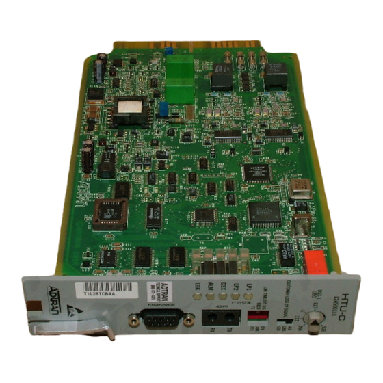
Figure 1. ADTRAN HTU-C M R
1. GENERAL
The ADTRAN 220/E220 HDSL Transceiver
Unit for the Central Office (HTU-C M R),
P/N 1245001L6, is the Central Office (CO) unit
used to deploy an HDSL T1 circuit using 4-wire
metallic facilities. The unit occupies one slot in a
standard 220 Office Repeater Bay or the ADTRAN
E220 Shelf.
DSX-1 signals are provided to and received from
the network while 2B1Q HDSL signals are provided
to the local loop. The ADTRAN HTU-C M R
works in conjunction with the ADTRAN HTU-R
and HREs to provide a DS1 service up to 36,000
feet on the local loop.
Issue 7, April 2001
H T U - C
1 L 6
1 2 4 5 0 0
53 3
39 9
D S X -1
E X T
LB O
26 6
0
13 3
AIS
L
LB K
SIG NA
SS OF
ER LO
CU ST OM
CD I
E N
A M I
D IS
E O U T
LB K T IM
B 8Z S
F T 1
T 1
H
L P 1
T X
D
S
L P 2
L
E
Q
R X
D S X
A L M
L B K
R
S
2
3
2
1
Advertisement
Table of Contents
Troubleshooting

Related Manuals for ADTRAN HTU-C M R


Summary of Contents for ADTRAN HTU-C M R
-
Page 1: Table Of Contents
Power Consumption Worksheet ......17 the network while 2B1Q HDSL signals are provided Table 10. Troubleshooting Guide ........17 to the local loop. The ADTRAN HTU-C M R Table 11. Product Specifications ........19 works in conjunction with the ADTRAN HTU-R Table A-1. -
Page 2: Installation
Code Input Output individual slot. Installation Code (IC) – The HTU-C M R contains onboard fuses. If a fuse Telecommunication Code (TC) – opens, it supplies a -48 Vdc voltage to the fuse Power Code (PC) alarm bus and all front panel indicators will turn off. - Page 3 Table 2. SW1 Rotary Switch Option Settings Switch Position Description SW1 ......DSX-1 Line Buildout Selects operation of the line buildout equalizer in series with the DSX-1 output. EXT ..Selects external line build-out 0 ....Line length from 0-133 feet of ABAM cable 133 ...
-
Page 4: Figure 2. Htu-C M R Switch Arrangement
Using Jumper P3, illustrated in Figure 2, the The HTU-C M R has five faceplate LEDs which HTU-C M R can be optioned for two different span indicate operational status. Table 5 defines these powering modes. By strapping P3 for “L” span LEDs. -
Page 5: Connections
3. CONNECTIONS The HTU-C M R is capable of span powering the HTU-R by applying simplex current to the local The 220/E220 HTU-C M R occupies one card slot loop. 10 to 125 mA of current is coupled onto the in a 220 Office Repeater Bay. -
Page 6: Hdsl System Testing
Detailed performance monitoring is provided by the logic level loopback at the point within the faceplate mounted RS-232 Control Port or the HTU-C M R where the DSX-1 signal passes into the ADTRAN HDSL Fuse/Alarm/Control Unit (HFAC) HDSL modulators. Figure 6 depicts all of the Shelf Controller. -
Page 7: Control Port Operation
The terminal interface operates at data rates from 1.2 kbps to 19.2 kbps. The asynchronous data The HTU-C M R provides a faceplate-mounted DB9 format is fixed at 8 data bits, no parity, and 1 stop connector that supplies an RS-232 interface for bit. - Page 8 HRE #1; type “H” a second time to view Low Voltage HDSL technology. The circuit the HRE Performance History Screen for HRE #2. includes an HTU-C M R, HTU-R, and two HREs. See Figure 11A for the HRE Performance History This scenario was chosen for inclusiveness of Screen.
- Page 9 25-character string of 0 or higher will support a bit error rate (BER) of alphanumeric characters. better than 10 . ADTRAN has defined the following as guidelines that correspond to the operation of the HTU-C faceplate LEDs labeled “LP1” and “LP2.”...
-
Page 10: Figure 8. Introductory Menu Screen
AT HTU-R Press “M” to view Main Menu. Figure 8. Introductory Menu Screen CIRCUIT ID: Circuit XXXXX 02/01/99 11:19:06 ADTRAN HDSL MAIN MENU 1) CURRENT SYSTEM STATUS 2) PERFORMANCE HISTORY 3) ADTRAN INFORMATION 4) LOOPBACK OPTIONS 5) SELF-TEST 6) PROVISIONING... -
Page 11: Figure 10. Current System Status Screen
CIRCUIT ID: Circuit XXXXX 02/01/99 11:14:38 LOOP #1 <NETWORK> LOOP #2 CURRENT SYSTEM STATUS LOOP #1 <CUSTOMER>LOOP #2 -------- HTU-C ---------- -------- HTU-R ---------- 02 dB 02 dB <-- LOSS --> 32 dB 32 dB <-- SYNC --> 000/00000 000/00000 <-- ES 15M/24H -->... -
Page 12: Figure 11. Performance History Screen
CIRCUIT ID: Circuit XXXXX 02/01/99 11:16:06 24 HOUR REGISTERS PERFORMANCE HISTORY 15 MINUTE REGISTERS --ES-SES-- --ES-SES-----ES-SES-- 00001 00000 <--CURRENT--> 000 000 01/31 ----- ----- <-- --> 11:15 000 000 07:15 --- --- 01/30 ----- ----- 11:00 001 000 07:00 --- --- 01/29 ----- ----- 10:45 --- --- 06:45 --- ---... -
Page 13: Figure 12. Provisioning Screen
CIRCUIT ID: Circuit XXXXX 02/01/99 11:18:17 PROVISIONING ___________________________________________________ PROVISIONS SETTINGS ------------------------------------------ * DSX-1 LINE BUILDOUT 0-133 FEET DS1 OUTPUT LEVEL 0 dB * DSX-1/DS1 LINE CODE B8ZS DSX-1 FRAMING DS1 FRAMING * LOOPBACK TIMEOUT NONE * CUSTOMER LOSS RESPONSE * LATCHING LOOPBACK MODE |___________________________________________________| Provisions marked with an asterisk (*) can be changed using switches on the HTU-C. -
Page 14: Figure 14. Self-Test Options Screen
CIRCUIT ID: Circuit XXXXX 02/01/99 11:17:51 SELF-TEST Press “S” to initiate HTU-C and HTU-R self-tests. Press “M” to return to the Main Menu. Figure 14. Self-Test Options Screen CIRCUIT ID: Circuit XXXXX 02/01/99 11:18:38 TROUBLESHOOTING DISPLAY _____ _____ _____ |HTU-C| |HRE 1| |HTU-R| --->|... -
Page 15: Figure 16. Set Time/Date/Circuit Id
CIRCUIT ID: Circuit XXXXX 02/01/99 11:12:52 SET TIME/DATE/CIRCUIT ID 1) SET TIME 2) SET DATE 3) SET CIRCUIT ID Choose an option by pressing the corresponding number. Press “M” to return to Main Menu. Figure 16. Set Time/Date/Circuit ID Screen 61245001L6-5G Section 61245001L6-5, Issue 7... -
Page 16: Hdsl Deployment Guidelines
6. HDSL DEPLOYMENT GUIDELINES Loop loss per Kft for other wire is summarized in The ADTRAN HDSL system is designed to provide Table 7. DS1 based services over loops designed to comply Table 7. HDSL Loss Values with carrier service area (CSA) guidelines. CSA (200 kHz cable loss in dB/kft at 135Ω) -
Page 17: Troubleshooting Procedures
7. TROUBLESHOOTING PROCEDURES Table 10 is a troubleshooting guide for the 220/ 2. Insert the HTU-C M R into an operational slot and check the LED indicators. When the unit is powered, at least E220 HTU-C M R. one LED will be on. -
Page 18: Product Specifications
Product specifications are detailed in Table 11. 10. WARRANTY AND CUSTOMER SERVICE ADTRAN will replace or repair this product within 10 years from the date of shipment if it does not meet its published specifications or fails while in service... - Page 19 DSX-1 Format ............Unframed, SF, ESF Power Tested with the ADTRAN Low-Voltage HRE (P/N 1244041L2) and the ADTRAN Low Voltage HTU-R (1245021L1). Total Power ..............-48 Vdc @ 200 mA with HTU-R -48 Vdc @ 300 mA with HTU-R and HRE -48 Vdc @ 510 mA with HTU-R and two HREs HTU-C M R Power Dissipation ........
- Page 20 Section 61245001L6-5, Issue 7 61245001L6-5G...
-
Page 21: Appendix Ahdsl Loopbacks
Appendix A HDSL Loopbacks HDSL MAINTENANCE MODES DDS Latching Loopback Operation If the unit is optioned for FT1 mode, then DDS This Appendix describes operation of the HDSL Latching Loopback operation is supported as system with regard to detection of in-band and ESF described in Bellcore TA-TSY-000077, Issue 3, facility data link loopback codes. - Page 22 Table A-1. HDSL Loopback Control Codes Type Source Code Name Abbreviated (N) ....3in7 (1110000) ..... Loopback data from network toward network in the HTU-R. (N) ....4in7 (1111000) ..... Loopback data from network toward network in the HTU-C. (N) ....2in6 (110000) ....Loopback data from network toward network in first HRE. (N) ....
- Page 23 Table A-2. Inband Addressable Loopback Codes Code and Function Response Arm ..........11000 (also known as a 2-in-5 pattern) The HTU-R will loop up towards the network. No AIS or errors will be sent as a result of this loopback. The HTU-C and HRE will arm. Disarm ...........
- Page 24 Section 61245001L6-5, Issue 7 61245001L6-5G...
Need help?
Do you have a question about the HTU-C M R and is the answer not in the manual?
Questions and answers