
Related Manuals for Eneo MPD-62M2812P0A


Summary of Contents for Eneo MPD-62M2812P0A
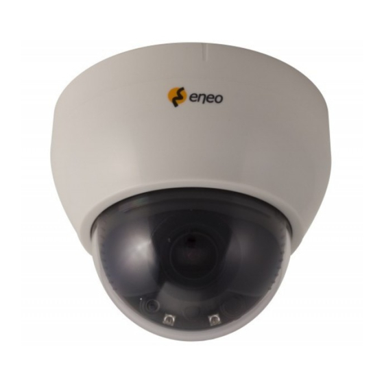
- Page 1 Quick Installation Guide 1/2.8” HD Dome, Fixed, WDR, Day&Night, 1920x1080, 12VDC, 2.8-12mm, Infrared, Indoor MPD-62M2812P0A...
-
Page 2: Table Of Contents
Table of content Parts supplied ......................5 Part names .........................6 Installation instructions ...................7 Pan & Tilt adjustments ...............................8 Power supply connections ............................9 Operating instructions ...................10 Using OSD controller ..............................10 Description of the OSD control operation ................... 10 Description of the Motorized ZOOM&FOCUS adjustment ............10 OSD menu startup .............................. - Page 3 Safety instructions General safety instructions • Before switching on and operating the system, rst read this safety advice and the operating instructions. • Keep the operating instructions in a safe place for later use. • Installation, commissioning and maintenance of the system may only be carried out by authorised individuals and in accordance with the installation instructions - ensuring that all applicable standards and guidelines are followed.
- Page 4 Class A device note This is a Class A device. This device can cause malfunctions in the living area; in such an event, the operator may need to take appropriate measures to compensate for these. WEEE (Waste Electronical & Electronic Equipment) Correct Disposal of This Product (Applicable in the European Union and other European countries with separate collection systems).
-
Page 5: Parts Supplied
Parts supplied • Dome Camera • Operating Instruction • Mounting Template • Easy Adaptor (Flat type) • Easy Adaptor (Tilted type) • Open Tool (1x) • Plastic Anchor: 6 x 30mm (3x) • Mounting Screw: 3.5 x 25mm (3x) • Video Sub-out Cable (1x) -
Page 6: Part Names
Part names Option: Easy Adaptor Tilted type Power Cable Easy Adaptor Flat type Dome Base Lens 3-Axis Gimbal OSD Menu Control board Dome Cover Bubble Shield Light Sensor Bubble IR LEDs... -
Page 7: Installation Instructions
Installation instructions CAUTION: The camera’s base should be attached to a structural object, such as concrete, hard wood, wall stud or ceiling rafter that supports the weight of the camera. If necessary use appro- priate mounting material (e.g. anchors) instead of the material enclosed with the camera. -
Page 8: Pan & Tilt Adjustments
Detach the dome camera from the Easy Adaptor Push the hook on the dome base and swing the dome base to counterclock wise. Then detach the dome camera from the installed easy adaptor. Open the dome cover 1. Insert wide side of Open Tool into the lock of Dome Cover. 2. -
Page 9: Power Supply Connections
Extended viewing angle Tilted Easy Adaptor (Option) CAUTION: Extreme care should be taken NOT to scratch the bubble dome surface while the camera installing or adjusting. Care should be taken the cable is NOT to be damaged, kinked or exposed in the hazardous area. Tighten enough the dome cover xing screws so that there should be NO gap between Lens hood and clear bubble to avoid the light in ow from IR LEDs. -
Page 10: Operating Instructions
Operating instructions Using OSD controller Setup menu can be accessed and controlled by OSD control joy stick on the side of the gimbal. Five commands are available with the joy stick. Video sub-out Connector OSD Control Joy Stick Description of the OSD control operation 1. -
Page 11: Osd Menu Startup
OSD menu startup Press the ‘OSD menu SET key’ down to access the setup menu mode. • EXIT : Enters ‘EXIT’ menu with save current setting or without save. • RETURN : Returns to the previous menu. MENU V0. XX 1. - Page 12 MODE WINDOW ZONE/USE, H/V-POS, H/V-SIZE BACKLIGHT NORMAL TARGET-BRT LOW, MIDDLE, HIGH LOW, MIDDLE, HIGH WEIGHT EXTERN SMART IR, ANTI-SAT., DELAY, IR LED CTL (AUTO, OFF)* AUTO SMART IR, ANTI-SAT., AGC THRES, AGC MARGIN, DELAY DAY & NIGHT COLOR B&W SMART IR, ANTI-SAT. AUTO, AUTOext, PRESET, MANUAL (C-TEMP, R/B-GAIN) COLOR COLOR GAIN...
-
Page 13: Further Information
Further information The manual is also available from the eneo web site at www.eneo-security.com. - Page 14 Inhaltsverzeichnis Lieferumfang ......................17 Bezeichnungen von Gerätekomponenten ............. 18 Installationsanweisungen ..................19 Einstellung von Schwenkung und Neigung ....................... 20 Stromversorgungsanschlüsse ..........................21 Betriebsanleitung ....................22 Bildschirmmenü-Steuerung verwenden ....................... 22 Beschreibung der Bedienung der Bildschirmsteuerung ..............22 Beschreibung der Einstellung für das motorisierte Zoom und Fokus ........22 Bildschirmmenü...
- Page 15 Sicherheitsanweisungen Sicherheitshinweise allgemein • Bevor Sie das System anschließen und in Betrieb nehmen, lesen Sie zuerst diese Sicherheitshinweise und die Betriebsanleitung. • Bewahren Sie die Betriebsanleitung sorgfältig zur späteren Verwendung auf. • Montage, Inbetriebnahme und Wartung des Systems darf nur durch dafür autorisierte Personen vorge- nommen und entsprechend den Installationsanweisungen - unter Beachtung aller mitgeltenden Normen und Richtlinien - durchgeführt werden.
- Page 16 • Bei abgedunkelter Umgebung und direktem Blick in den IR-Scheinwerfer ist ein Sicherheitsabstand von > 1 m zum Scheinwerfer einzuhalten. • Unsichtbare LED Strahlung nicht direkt mit optischen Instrumenten (z.B. Lupe, Vergrößerungsglas oder Mikroskop) betrachten, da sie eine Augengefährdung verursachen kann, LED Klasse 1M. •...
-
Page 17: Lieferumfang
Lieferumfang • Dome-Kamera • Betriebsanleitung • Bohrschablone • Einfacher Adapter (flach) • Einfacher Adapter (keilförmig) • Universalwerkzeug (1x) • Kunststoffdübel: 6 x 30mm (3x) • Befestigungsschraube: 3,5 x 25 mm (3x) • Video Sub-out Kabel (1x) -
Page 18: Bezeichnungen Von Gerätekomponenten
Bezeichnungen von Gerätekomponenten Optional: Einfacher Adapter (keilförmig) Netzkabel/Videokabel Einfacher Adapter flach Dome-Basis Objektiv 3-Achsen- Aufhängering Steuerung des OSD-Menüs Dome-Abdeckung Sonnenschutzdach für Kuppel Lichtsensor Kuppel IR LEDs... -
Page 19: Installationsanweisungen
Installationsanweisungen ACHTUNG: Die Kamerahalterung sollte an einem Bauelement wie etwa Beton, Hartholz, einem Wandständer oder Deckenbalken befestigt werden, welches das Gewicht der Kamera trägt. Verwenden Sie, falls erforderlich, geeignetes Befestigungsmaterial (z.B. Dübel) anstelle des mitgelieferten Materials. 1. Bohren Sie drei Löcher zur Montage an der Decke oder an der Wand. 2. -
Page 20: Einstellung Von Schwenkung Und Neigung
Trennen der Dome-Kamera vom einfachen Adapter Drücken Sie auf den Haken auf der Dome-Basis und drehen Sie die Dome-Basis gegen den Uhrzeigersinn. Trennen Sie anschließend die Dome-Kamera vom installierten einfachen Adapter. 1. Stecken Sie die breite Seite des Universalwerkzeugs in den Verschluss der Dome-Abdeckung. -
Page 21: Stromversorgungsanschlüsse
Erweiterter Betrachtungswinkel Keilförmiger einfacher Adapter (Option) ACHTUNG: Achten Sie besonders darauf, die Abdeckkuppel der Dome- Kamera während der Installation oder der Einstellung NICHT zu verkratzen. Achten Sie besonders darauf, die IR-LEDs nicht zu beschädigen. Es muss sorgfältig darauf geachtet werden, das Kabel NICHT zu beschädigen, zu knicken oder Gefahrenbereichen auszusetzen. -
Page 22: Betriebsanleitung
Betriebsanleitung Bildschirmmenü-Steuerung verwenden Zugri und Steuerung des Kon gurationsmenüs können über den OSD Joystick erfolgen, der sich an der Seite des Aufhängerings be ndet. Fünf Befehle stehen mit dem Joystick zur Verfügung. Video Sub-out Anschluss Joystick zur Bildschirmmenü-Steuerung Beschreibung der Joystick-Bedienung 1. -
Page 23: Bildschirmmenü Starten
Bildschirmmenü starten Drücken Sie die Taste ‘SET-Taste für Bildschirmmenü’, um in das Setup-Menü zu gelangen. • EXIT : Öffnet das EXIT-Menü mit der Möglichkeit die aktuellen Einstellungen zu speichern oder zu verwerfen. • RETURN (ZURÜCK): Kehrt zum vorherigen Menü zurück. MENU V0. - Page 24 MODUS WINDOW ZONE/USE, H/V-POS, H/V-SIZE BACKLIGHT (HINTER- NORMAL GRUNDBELEUCHTUNG) ZIEL-HELL NIEDRIG, MITTE, HOCH NIEDRIG, MITTE, HOCH GEWICHTUNG EXTERN SMART IR, ANTI-SAT., DELAY, IR LED CTL (AUTO, AUS)* AUTO SMART IR, ANTI-SAT., AGC THRES, AGC MARGIN, DELAY TAG/NACHT FARBE B&W (S/W) SMART IR, ANTI-SAT.
-
Page 25: Weitere Informationen
Weitere Informationen Dieses Handbuch ist auch auf der eneo-Webseite unter www.eneo-security.com verfügbar. - Page 26 Contenu Matériel livré ......................31 Noms des pièces ..................... 32 Instructions d'installation ..................33 Réglages Panoramique/Inclinaisons ....................... 34 Connexions d'alimentation ..........................35 Mode d'emploi ....................... 36 Utilisation d'une commande OS ........................36 Description de l'opération de commande OSD ................36 Description de l'ajustement motorisé...
- Page 27 Instructions de sécurité Consignes de sécurité générales • Avant de brancher et de mettre en service le système, veuillez lire d'abord ces consignes de sécurité ainsi que la notice d'instructions. • Conservez soigneusement la notice d'instructions en vue d'une utilisation ultérieure. •...
- Page 28 • Une distance de sécurité > 1 m doit être respectée par rapport au projecteur dans un environnement sombre, quand on regarde directement dans le projecteur IR. • Les rayons invisibles des LED ne doivent pas être observés directement avec des instruments optiques (par ex.
-
Page 29: Matériel Livré
Matériel livré • Caméra dôme • Mode d'emploi • Gabarit de perçage • Easy Adaptor (type plat) • Easy Adaptor (type incliné) • Outil d'ouverture (1x) • Chevilles en plastique : 6 x 30mm (3x) • Vis de fixation : 3.5 x 25mm (3x) •... -
Page 30: Noms Des Pièces
Noms des pièces Option : adaptateur facile Type incliné Câble d'alimentation / vidéo Adaptateur facile Type plat Base du dôme Objectif Cardan sur 3 axes Tableau de commande du menu OSD Couvercle du dôme Dôme à coupole Capteur de lumière Coupole DEL IR... -
Page 31: Instructions D'installation
Instructions d'installation ATTENTION: La base de la caméra doit être xée à une surface solide, comme du bois dur, un mur, pilier ou poutre au plafond apte à supporter le poids de la caméra dôme. Si nécessaire, utiliser un matériel de xation (ancrages) plus adéquat au lieu du matériel fourni avec la caméra. -
Page 32: Réglages Panoramique/Inclinaisons
Démonter la caméra dôme de l'Easy Adaptor Pousser le crochet de la base et pivoter la base du dôme dans le sens inverse des aiguilles de la montre. Ensuite, la caméra dôme peut être retirée de l'Easy Adaptor installé. Ouvrir le cache de l’objectif 1. -
Page 33: Connexions D'alimentation
Angle de vision étendue de la caméra Easy Adaptor incliné (Option) ATTENTION: Il faudra veiller à ne pas éra er la surface de la coupole lors de l'installation ou le réglage de la caméra. Il faudra veiller à ne pas appliquer de la force aux LED IR. Veillez à... -
Page 34: Mode D'emploi
Mode d'emploi Utilisation d'une commande OS L'accès et la commande du menu de con guration peut s'e ectuer à l'aide du joystick de commande OSD situé sur le côté du cardan. Cinq fonctions de commande sont disponibles avec la manette. Connecteur sous-sortie vidéo Manette de commande OSD Description du fonctionnement de la manette de contrôle... -
Page 35: Démarrage Du Menu Osd
Démarrage du menu OSD Appuyez sur la touche SET du menu OSD pour accéder au mode menu de con guration. • EXIT (SORTIE) : active le menu 'EXIT' avec enregistrement du réglage actuel ou sans enregistrement. • RETURN (RETOUR) : retourne au menu précédent. MENU V0. - Page 36 MODE WINDOW ZONE/USE, H/V-POS, H/V-SIZE Contre-jour NORMAL TARGET-BRT MOYEN, ÉLEVÉ, BAS MOYEN, ÉLEVÉ, BAS POIDS EXTERNE SMART IR, ANTI-SAT., DELAY, IR LED CTL (AUTO, OFF)* AUTO SMART IR, ANTI-SAT., AGC THRES, AGC MARGIN, DELAY JOUR & NUIT Couleur B&W SMART IR, ANTI-SAT. AUTO, AUTOext, PRESET, MANUEL (C-TEMP, R/B-GAIN) Couleur Gain de Couleur...
-
Page 37: Complément D'information
Complément d'information Le manuel complet est également proposé sur le site Web d’eneo : www.eneo-security.com... - Page 38 Indice Parti fornite ......................41 Denominazione dei componenti ................42 Istruzioni per l'installazione .................. 43 Regolazione della panoramica e dell'inclinazione ..................44 Collegamento all'alimentazione ........................45 Istruzioni per l'uso ....................46 Utilizzo del controller OSD ........................... 46 Descrizione del funzionamento del comando OSD ..............46 Descrizione della regolazione motorizzata dello zoom e della messa a fuoco....
- Page 39 Istruzioni per la sicurezza Istruzioni generali per la sicurezza • Prima di collegare e mettere in funzione il sistema, leggete le istruzioni per la sicurezza e le istruzioni per l'uso. • Conservate con cura le istruzioni per l'uso per un eventuale utilizzo futuro. •...
- Page 40 • Deve essere mantenuto un margine di sicurezza di > 1 m dal proiettore se si guarda direttamente nel proiettore IR in un ambiente buio. • Non guardare direttamente le radiazioni LED invisibili utilizzando strumenti ottici (ad es. lente, lente di ingrandimento o microscopio) per prevenire danni agli occhi ( LED classe 1M).
-
Page 41: Parti Fornite
Parti fornite • Telecamera dome • Istruzioni per l'uso • Dima di montaggio • Easy Adaptor (tipo piatto) • Easy Adaptor (tipo inclinato) • Attrezzo di apertura (1x) • Tasselli di plastica: 6 x 30 mm (3x) • Viti di montaggio: 3,5 x 25 mm (3x) •... -
Page 42: Denominazione Dei Componenti
Denominazione dei componenti Opzione: Easy Adaptor tipo inclinato Cavo di alimentazione / video Easy Adapter Tipo piatto Base telecamera dome Obbiettivo Staffa a ruotare a 3 assi Scheda di controllo del menu OSD Coperchio telecamera Protezione cupola Sensore luce Cupola LED IR... -
Page 43: Istruzioni Per L'installazione
Istruzioni per l'installazione ATTENZIONE: The camera’s base should be attached to a structural object, such as concrete, hard wood, wall stud or ceiling rafter that supports the weight of the camera. Se necessario utilizzare materiale di montaggio adatto (ad es. tasselli) al posto del materiale fornito con la telecamera. -
Page 44: Regolazione Della Panoramica E Dell'inclinazione
Staccare la telecamera dome camera dall'Easy Adaptor. Spingere il gancio sulla base della cupola e girare la base della cupola in senso antiorario. Quindi staccare la telecamera dome dall'Easy Adaptor installato. Apertura del coperchio della cupola 1. Inserire il lato largo dell'attrezzo di apertura nella fessura del coperchio della cupola. 2. -
Page 45: Collegamento All'alimentazione
Angolo di visualizzazione esteso Easy Adaptor inclinato (optional) ATTENZIONE: prestare estrema attenzione a NON gra are la super cie della cupola durante le operazioni di installazione o regolazione. Prestare estrema attenzione a NON fare forza sui LED IR. Fare attenzione a NON danneggiare, piegare o avvicinare il cavo alla zona di pericolo. -
Page 46: Istruzioni Per L'uso
Istruzioni per l'uso Utilizzo del controller OSD È possibile accedere al menu di impostazione e controllarlo con il joystick di comando OSD a lato della sta a. Tramite il joystick sono disponibili cinque comandi. Connettore Sub-out video Joystick di comando dell'OSD Descrizione del funzionamento del joystick 1. -
Page 47: Avvio Del Menu Osd
Avvio del menu OSD Premere il tasto 'OSD menu SET' verso il basso per accedere alla modalità del menu di impostazione. • EXIT: consente di accedere al menu 'EXIT' con l'impostazione di salvataggio corrente o senza salvataggio. • RETURN (Indietro): ritorna al menu precedente. MENU V0. - Page 48 MODE WINDOW ZONE/USE, H/V-POS, H/V-SIZE BACKLIGHT NORMALE TARGET-BRT LOW, MIDDLE, HIGH LOW, MIDDLE, HIGH WEIGHT EXTERN SMART IR, ANTI-SAT., DELAY, IR LED CTL (AUTO, OFF)* AUTO SMART IR, ANTI-SAT., AGC THRES, AGC MARGIN, DELAY DAY & NIGHT COLOR B&W SMART IR, ANTI-SAT. AUTO, AUTOext, PRESET, MANUAL (C-TEMP, R/B-GAIN) COLOR COLOR GAIN...
-
Page 49: Altre Informazioni
Altre informazioni Il manuale è disponibile anche sul sito web di eneo all'indirizzo www.eneo-security.com. - Page 52 VIDEOR E. Hartig GmbH Exclusive distribution through specialised trade channels only. VIDEOR E. Hartig GmbH Carl-Zeiss-Straße 8 63322 Rödermark/Germany Tel. +49 (0) 6074 / 888-0 Technical changes reserved Fax +49 (0) 6074 / 888-100 www.videor.com...
Need help?
Do you have a question about the MPD-62M2812P0A and is the answer not in the manual?
Questions and answers