Advertisement
Table of Contents
Harbor Breeze® is a registered trademark
of LF, LLC. All Rights Reserved.
ATTACH YOUR RECEIPT HERE
Purchase Date _________________________
Questions, problems, missing parts? Before returning to your retailer, call our customer
service department at 1-800-643-0067, 8 a.m. - 8 p.m., EST, Monday - Sunday.
BM19240
1
ITEM #1461038
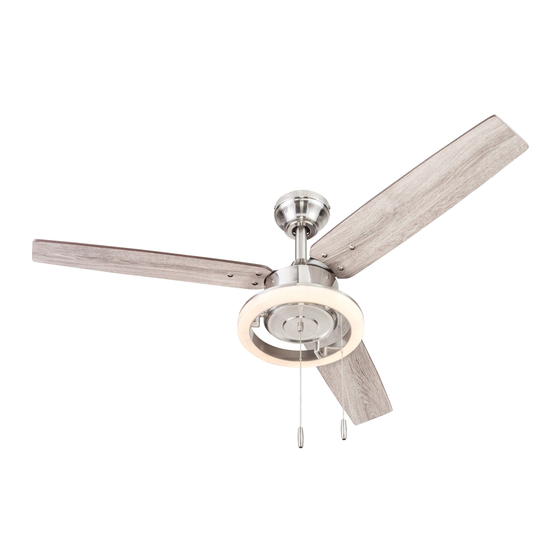
WELLSBORO
CEILING FAN
MODEL #42072
Español p. 19
Advertisement
Table of Contents

Subscribe to Our Youtube Channel
Related Manuals for Harbor Breeze WELLSBORO 42072


Summary of Contents for Harbor Breeze WELLSBORO 42072
- Page 1 ITEM #1461038 WELLSBORO CEILING FAN MODEL #42072 Español p. 19 Harbor Breeze® is a registered trademark of LF, LLC. All Rights Reserved. ATTACH YOUR RECEIPT HERE Purchase Date _________________________ Questions, problems, missing parts? Before returning to your retailer, call our customer service department at 1-800-643-0067, 8 a.m.
-
Page 2: Table Of Contents
TABLE OF CONTENTS Package Contents ..............3 Hardware Contents . -
Page 3: Package Contents
PACKAGE CONTENTS PART DESCRIPTION QUANTITY Downrod Downrod Pin (preassembled to Downrod [A]) Downrod Clip (preassembled to Downrod [A]) Mounting Bracket (preassembled to Canopy [E]) Canopy Canopy Cover (preassembled to Canopy [E]) Motor Assembly Fitter Plate Yoke Cover Light Kit Mounting Bracket Screw (preassembled to Mounting Bracket [D]) Blade Fitter Plate Screw (preassembled to Fitter Plate [H]) Blade Arm... -
Page 4: Hardware Contents
(shown actual size) HARDWARE CONTENTS Wire Connector Blade Screw Blade Washer Pull Chain Extension Qty. 3 Qty. 9 Qty. 9 Qty. 2 + 1 extra + 1 extra +1 extra Screw Cap Motor Screw Qty. 9 1 extra + 1 extra... -
Page 5: Safety Information
SAFETY INFORMATION Please read and understand this entire manual before attempting to assemble, operate or install the product. • Before you begin installing the fan, disconnect the power by removing fuses or turning off the circuit breakers. • Make sure all electrical connections comply with local codes, ordinances, the National Electrical Code and ANSI/NFPA 70-199. -
Page 6: Preparation
SAFETY INFORMATION CAUTION: Read all instructions and safety information before installing your new fan. Review the accompanying assembly diagrams. CAUTION: Be sure the outlet box is properly grounded or that a ground (green or bare) wire is present. CAUTION: Carefully check all screws, bolts and nuts on the fan motor assembly to ensure they are secured. -
Page 7: Initial Installation
INITIAL INSTALLATION 1. Turn off the circuit breakers and the wall switch to the fan supply line leads. DANGER: Failure to disconnect the power supply prior to installation may result in serious injury or death. 2. Determine the mounting method to use. Standard Mounting is best suited for ceilings 8 ft. - Page 8 INITIAL INSTALLATION 4. Loosen all four preassembled mounting bracket screws (K), then completely remove the two mounting bracket screws (K) from the round holes in the canopy (E). Set aside for later use. Detach mounting bracket (D) from the canopy (E). 5.
- Page 9 INITIAL INSTALLATION 7. Remove the downrod clip (C) and downrod pin (B) from the downrod (A). Then partially loosen the set screws (P) in the yoke at the top of the motor assembly (G). Yoke 8. Insert the downrod (A) through the canopy (E) and yoke cover (I).
- Page 10 INITIAL INSTALLATION 10. Depending on the length of downrod you use, you may need to cut the lead wires back to simplify the wiring. If you decide to cut back the lead wires, pull them all the way through the top of the downrod. Then measure 8 inches of lead wire and cut the excess wire off with wire cutters (not included).
-
Page 11: Wiring
WIRING WARNING: To reduce the risk of fire, electrical shock or personal injury, wire connectors provided with this fan are designed to accept only one 12-gauge house wire and two lead wires from the fan. If your house wire is larger than 12-gauge and there is more than one house wire to connect to the two fan lead wires, consult an electrician for the proper size wire connectors to use. -
Page 12: Final Installation
FINAL INSTALLATION 1. Align the canopy (E) over the loosened mounting bracket screws (K) preassembled on mounting bracket (D). Place the keyholes of the canopy (E) onto the mounting bracket screws (K) and rotate the canopy (E) clockwise. 2. Secure the canopy (E) with the mounting bracket screws (K) previously removed (Step 4, page 8). - Page 13 FINAL INSTALLATION Attach the blades (L) to the blade arms (N) using the blade screws (BB), blade washers (CC) and screw caps (LL). Hardware Used Blade Screw Blade Washer Screw Cap 4. Install the blade arm (N) to the topside of the motor assembly (G) with motor screws (O) previously removed (Step 6, page 8).
- Page 14 FINAL INSTALLATION 6. Remove the three fitter plate screws (M) preassembled to the fitter plate (H). Then, connect the 9-pin connector from the fitter plate (H) to the 9-pin connector from the light kit (J). Secure the light kit (J) to the fitter plate (H) using the previously removed fitter plate screws (M).
-
Page 15: Operating Instructions
OPERATING INSTRUCTIONS 1. The fan pull chain has four positions to control the fan speed. One pull is HIGH, two is MEDIUM, three is LOW, and four turns the fan OFF. The pull chain in the center of the light kit (J) turns the lights ON and OFF. Fan Pull Chain Light Pull... -
Page 16: Care And Maintenance
CARE AND MAINTENANCE At least twice each year, lower the canopy to check the downrod assembly, and then tighten all screws on the fan. Clean the motor assembly with only a soft brush or lint-free cloth to avoid scratching the finish. Clean the blades with a lint-free cloth. Important: Shut off the main power supply before you begin any maintenance task. -
Page 17: Limited Lifetime Warranty
TROUBLESHOOTING PROBLEM POSSIBLE CAUSE CORRECTIVE ACTION 1. The light kit wire plugs are not 1. Ensure the 9-pin connectors in the light kit are connected properly. connected properly. The fan operates correctly, but the 2. Turn the power off and check all 2. -
Page 18: Replacement Parts List
REPLACEMENT PARTS LIST For replacement parts, call the customer service department at 1-800-643-0067, 8 a.m. - 8 p.m., EST, Monday - Sunday. PART DESCRIPTION PART # Downrod 4L000007500 Mounting Bracket 4L000006410 Canopy 4L000004350 Canopy Cover 4L000002900 Yoke Cover 4L000000230 Light Kit 4L000011440 Blade (x3) 4L085380001...
Need help?
Do you have a question about the WELLSBORO 42072 and is the answer not in the manual?
Questions and answers