Advertisement
Table of Contents
- 1 Ceiling Fan
- 2 Table of Contents
- 3 Package Contents
- 4 Hardware Contents
- 5 Safety Information
- 6 Preparation
- 7 Initial Installation
- 8 Wiring
- 9 Final Installation
- 10 Operating Instructions
- 11 Care and Maintenance
- 12 Troubleshooting
- 13 Limited Lifetime Warranty
- 14 Replacement Parts List
- Download this manual
Harbor Breeze® is a registered trademark
of LF, LLC. All Rights Reserved.
ATTACH YOUR RECEIPT HERE
Purchase Date _________________________
Questions, problems, missing parts? Before returning to your retailer, call our customer
service department at 1-800-643-0067, 8 a.m. - 6 p.m., EST, Monday - Thursday, 8 a.m. - 5 p.m.,
EST, Friday.
EB16198
BUILDER'S SERIES
1
ITEM #0807431
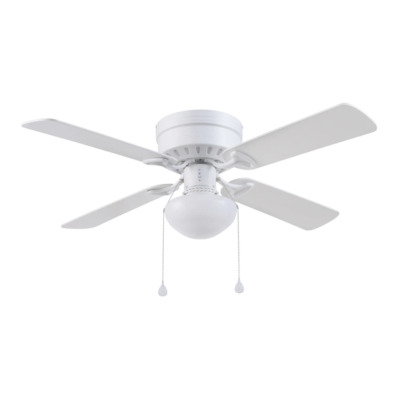
CEILING FAN
MODEL #40680
Español p. 18
Advertisement
Table of Contents

Subscribe to Our Youtube Channel
Related Manuals for Harbor Breeze 40680


Summary of Contents for Harbor Breeze 40680
-
Page 1: Ceiling Fan
ITEM #0807431 BUILDER’S SERIES CEILING FAN MODEL #40680 Harbor Breeze® is a registered trademark of LF, LLC. All Rights Reserved. Español p. 18 ATTACH YOUR RECEIPT HERE Purchase Date _________________________ Questions, problems, missing parts? Before returning to your retailer, call our customer service department at 1-800-643-0067, 8 a.m. -
Page 2: Table Of Contents
TABLE OF CONTENTS Package Contents ..............3 Hardware Contents . -
Page 3: Package Contents
PACKAGE CONTENTS PART DESCRIPTION QUANTITY Upper Mounting Bracket Lower Mounting Bracket (preassembled to Motor [C]) Motor Switch Housing (preassembled to Motor [C]) Light Kit (preassembled to the Switch Housing [D]) Motor Housing Blade Arm Blade Glass Globe Bulb Lower Bracket Screw (preassembled to Lower Mounting Bracket [B]) Thumbscrew (preassembled to Light Kit [E]) Motor Screw (preassembled to Motor [C]) 8 + 1 extra... -
Page 4: Hardware Contents
HARDWARE CONTENTS (shown actual size) Blade Screw Blade Washer Pull Chain Extension Wire Connector Qty. 12 + 1 extra Qty. 12 + 1 extra Qty. 2 Qty. 4... -
Page 5: Safety Information
SAFETY INFORMATION Please read and understand this entire manual before attempting to assemble, operate or install the product. • Before you begin installing the fan, disconnect the power by removing fuses or turning off the circuit breakers. • Make sure all electrical connections comply with local codes, ordinances, the National Electrical Code and ANSI/NFPA 70-199. Hire a qualified electrician or consult a do-it-yourself wiring handbook if you are unfamiliar with installing electrical wiring. -
Page 6: Preparation
SAFETY INFORMATION CAUTION: Read all instructions and safety information before installing your new fan. Review the accompanying assembly diagrams. CAUTION: Be sure the outlet box is properly grounded or that a ground (green or bare) wire is present. CAUTION: Carefully check all screws, bolts and nuts on the fan motor assembly to ensure they are secured. -
Page 7: Initial Installation
INITIAL INSTALLATION 1. Turn off the circuit breakers and the wall switch to the fan supply line leads. DANGER: Failure to disconnect the power supply prior to installation may result in serious injury or death. 2. This fan is intended for Flushmount installations. Standard Mounting, Angled Mounting and Closemount installations are not available. - Page 8 INITIAL INSTALLATION 4. Secure the upper mounting bracket (A) to the outlet box (not included) using screws and washers provided with the outlet box. CAUTION: It is very important you use the proper hardware when installing the upper mounting bracket (A) as it will support the fan.
-
Page 9: Wiring
WIRING WARNING: To reduce the risk of fire, electrical shock or personal injury, wire connectors provided with this fan are designed to accept only one 12-gauge house wire and two lead wires from the fan. If your house wire is larger than 12 gauges and/or there is more than one house wire to connect to the two fan lead wires, consult an electrician for the proper size wire connectors to use. -
Page 10: Final Installation
FINAL INSTALLATION 1. Temporarily lift the motor housing (F) to the upper mounting bracket (A) to determine which two motor housing screws (N) preassembled in the sides of the upper mounting bracket (A) align with the slotted holes in the top edge of the motor housing (F). Partially loosen the two motor housing screws (N) that align with the slotted holes. - Page 11 FINAL INSTALLATION 4. Remove the 10 preassembled motor screws (M) from the underside of the motor (C). Insert two motor screws (M) in each blade arm (G) and install the blade arm (G) to the underside of the motor (C) with motor screws (M). Tighten with Phillips screwdriver.
- Page 12 FINAL INSTALLATION 7. Turn on power supply to the fan. Assembly is complete.
-
Page 13: Operating Instructions
OPERATING INSTRUCTIONS 1. The fan pull chain has four positions to control fan speed. One pull is HIGH, two is MEDIUM, three is LOW and four turns the fan OFF. The light pull chain has two positions to control the light, ON and OFF. -
Page 14: Care And Maintenance
CARE AND MAINTENANCE At least twice each year, lower the motor housing and tighten all screws on the fan. Clean the motor housing with only a soft brush or lint-free cloth to avoid scratching the finish. Clean the blades with a lint-free cloth. You may occasionally apply a light coat of furniture polish to wood blades for added protection. - Page 15 TROUBLESHOOTING PROBLEM POSSIBLE CAUSE CORRECTIVE ACTION 1. The blades and/or blade are 1. Check and tighten all screws that loose. hold the fan blades to the blade arms and the blade arms to the motor. 2. The blades are unbalanced. 2.
-
Page 16: Limited Lifetime Warranty
LIFETIME LIMITED WARRANTY The manufacturer warrants this fan to be free from defects in workmanship and materials present at time of shipment from the factory for a lifetime from the date of purchase by the original purchaser. The retailer also warrants that all other fan parts, excluding any glass or plastic blades, to be free from defects in workmanship and material at the time of shipment from the factory for a period of one year after the date of purchase by the original purchaser. -
Page 17: Replacement Parts List
REPLACEMENT PARTS LIST For replacement parts, call the customer service department at 1-800-643-0067, 8 a.m. - 6 p.m., EST, Monday - Thursday, 8 a.m. - 5 p.m., EST, Friday. PART DESCRIPTION PART # Upper Mounting Bracket 807431-A Motor Housing 807431-F Blade Arm 807431-G Blade...
Need help?
Do you have a question about the 40680 and is the answer not in the manual?
Questions and answers