Table of Contents
Advertisement
Quick Links
Harbor Breeze® is a registered trademark
of LF, LLC. All Rights Reserved.
ATTACH YOUR RECEIPT HERE
Purchase Date ___________________________
Questions, problems, missing parts? Before returning to your retailer, call our customer
service department at 1-800-643-0067, 8 a.m. - 8 p.m., EST, Monday - Sunday.
RR20275
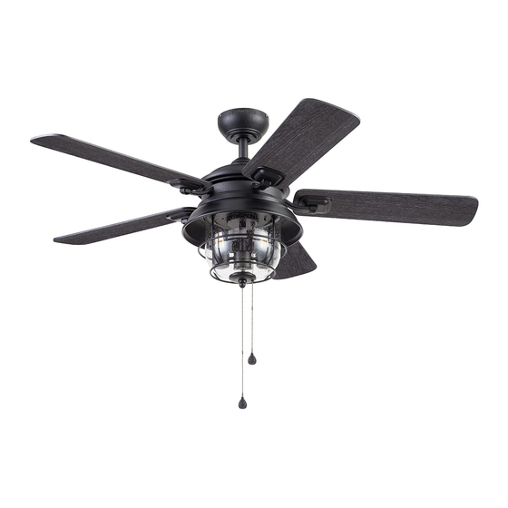
ALTISSA CEILING FAN
1
ITEM #0883775, 2758998
MODEL #42079, 42242
Español p. 22
LISTED FOR
DAMP LOCATION
Advertisement
Table of Contents

Related Manuals for Harbor Breeze 42079


Summary of Contents for Harbor Breeze 42079
- Page 1 ITEM #0883775, 2758998 ALTISSA CEILING FAN MODEL #42079, 42242 Español p. 22 Harbor Breeze® is a registered trademark of LF, LLC. All Rights Reserved. LISTED FOR DAMP LOCATION ATTACH YOUR RECEIPT HERE Purchase Date ___________________________ Questions, problems, missing parts? Before returning to your retailer, call our customer service department at 1-800-643-0067, 8 a.m.
-
Page 2: Table Of Contents
TABLE OF CONTENTS Package Contents ..............3 Hardware Contents . -
Page 3: Package Contents
PACKAGE CONTENTS PART DESCRIPTION QUANTITY Downrod Downrod Pin (preassembled to Downrod [A]) Downrod Clip (preassembled to Downrod [A]) Mounting Bracket (preassembled to Canopy [E]) Canopy Canopy Cover (preassembled to Canopy [E]) Yoke Cover Light Pan Glass Bowl Motor Assembly Set Screw (preassembled to Motor Assembly [J]) Fitter Plate (preassembled to Motor Assembly [J]) Fitter Plate Screw (preassembled to Fitter Plate [L]) Light Kit... -
Page 4: Hardware Contents
HARDWARE CONTENTS (shown actual size) Wire Connector Blade Screw Blade Washer Pull Chain Extension Motor Screw Qty. 3 Qty. 15 Qty. 15 Qty. 2 Qty. 15 + 1 extra + 1 extra + 1 extra + 1 extra... -
Page 5: Safety Information
SAFETY INFORMATION Please read and understand this entire manual before attempting to assemble, operate or install the product. • Before you begin installing the fan, disconnect the power by removing fuses or turning off the circuit breakers. • Make sure all electrical connections comply with local codes, ordinances, the National Electrical Code and ANSI/NFPA 70-199. -
Page 6: Preparation
SAFETY INFORMATION CAUTION: Be sure the outlet box is properly grounded or that a ground (green or bare) wire is present. CAUTION: Carefully check all screws, bolts and nuts on the fan motor assembly to ensure they are secured. CAUTION: This device complies with Part 15 of the FCC Rules. Operation is subject to the following two conditions: (1) this device may not cause interference, and (2) this device must accept any interference, including interference that may cause undesired operation of the device. -
Page 7: Initial Installation
INITIAL INSTALLATION 1. Turn off the circuit breakers and the wall switch to the fan supply line leads. DANGER: Failure to disconnect the power supply prior to installation may result in serious injury or death. 2. Determine the mounting method to use. Standard Mounting is best suited for ceilings 8 ft. - Page 8 INITIAL INSTALLATION 4. Loosen all four preassembled mounting bracket screws (V), then completely remove the two mounting bracket screws (V) from the round holes of canopy (E). Set aside for later use. Detach mounting bracket (D) from canopy (E). 5. Secure the mounting bracket (D) to the outlet box Standard (not included) using screws and washers provided Mount...
-
Page 9: Standard Or Angle Mounting Instructions
STANDARD OR ANGLE MOUNTING INSTRUCTIONS 1. Remove the downrod clip (C) and downrod pin (B) from the downrod (A). Then partially loosen the set screws (K) in the yoke at the top of the motor assembly (J). 2. Insert the downrod (A) through the canopy (E) and yoke cover (G). - Page 10 STANDARD OR ANGLE MOUNTING INSTRUCTIONS 4. Depending on the length of downrod you use, you may need to cut the lead wires back to simplify the wiring. If you decide to cut back the lead wires, it is suggested you do so in the following manner: Take the lead wires and make sure you have pulled them all the way 8 in.
-
Page 11: Wiring
WIRING WARNING: To reduce the risk of fire, electrical shock or personal injury, wire connectors provided with this fan are designed to accept only one 12-gauge house wire and two lead wires from the fan. If your house wire is larger than 12-gauge and/or there is more than one house wire to connect to the two fan lead wires, consult an electrician for the proper size wire connectors to use. -
Page 12: Final Installation
FINAL INSTALLATION 1. Align the canopy (E) over the loose mounting bracket screws (V) preassembled on mounting bracket (D). Place the J-shaped slot of the canopy (E) onto the mounting bracket screws (V) and rotate the canopy (E) clockwise. J-shaped Slot 2. - Page 13 FINAL INSTALLATION 4. Insert blade arm (R) through slots in the side of the motor assembly (J). Align the holes of one blade arm (R) with three motor screw holes in underside of the motor assembly (J). Secure with three motor screws (XX).
- Page 14 FINAL INSTALLATION 7. Remove one and loosen the other two light kit screws (X) from the underside of the light pan (H). 8. Connect the 9-pin connector from the fan to the 9-pin connector from the light kit (N). 9-pin Connector 9.
- Page 15 FINAL INSTALLATION 10. Install the bulbs (P) into the sockets on the light kit (N). Then, remove the finial (U) and hex nut (T) from threaded rod at the bottom of the light kit (N). 11. Lift the glass globe (I) over the threaded rod on light kit (N).
- Page 16 FINAL INSTALLATION 13. Attach the pull chain extensions (DD) or custom pull chain extensions (not included) to the fan and light pull chains. Hardware Used Pull Chain Extension Light Pull Chain Fan Pull Chain 14. Turn on power supply to the fan. Assembly is complete.
-
Page 17: Operating Instructions
OPERATING INSTRUCTIONS 1. Using a ceiling fan will allow you to raise your thermostat setting in the summer and lower your thermostat setting in the winter without feeling a difference in your comfort. Note: To access the reverse switch, remove the glass bowl (I) and light frame (O).The reverse switch is Reverse located on light kit (N). -
Page 18: Care And Maintenance
CARE AND MAINTENANCE At least twice each year, tighten all screws on the fan. Clean the motor housing with only a soft brush or lint-free cloth to avoid scratching the finish. Clean the blades with a lint-free cloth. Bulb Replacement: Use 60-watt max. E26-base LED, CFL or incandescent bulbs. Halogen bulbs are not recommended for this item. - Page 19 TROUBLESHOOTING PROBLEM POSSIBLE CAUSE CORRECTIVE ACTION 1. The blades are loose. 1. Check and tighten all screws that hold the fan blades to the blade arms and the motor. 2. There is a cracked blade. 2. Replace the cracked blade. 3.
-
Page 20: Limited Lifetime Warranty
LIMITED LIFETIME WARRANTY The manufacturer warrants this fan to be free from defects in workmanship and materials present at time of shipment from the factory for a lifetime from the date of purchase by the original purchaser. The retailer also warrants that all other fan parts, excluding any glass or plastic blades, to be free from defects in workmanship and material at the time of shipment from the factory for a period of one year after the date of purchase by the original purchaser. -
Page 21: Replacement Parts List
REPLACEMENT PARTS LIST For replacement parts, call the customer service department at 1-800-643-0067, 8 a.m. - 8 p.m., EST, Monday - Sunday. 0883775 2758998 PART DESCRIPTION PART # PART # Downrod 4L000011680 4L000013980 Mounting Bracket 4L000011690 4L000014050 Canopy 4L000011700 4L000014020 Canopy Cover 4L000011080 4L000014030...
Need help?
Do you have a question about the 42079 and is the answer not in the manual?
Questions and answers