Advertisement
Table of Contents
HARBOR BREEZE and logo design are trademarks or
registered trademarks of LF, LLC. All rights reserved.
ATTACH YOUR RECEIPT HERE
Purchase Date _________________________
Questions, problems, missing parts? Before returning to your retailer, call our customer
service department at 1-888-251-1003, 8 a.m. - 8 p.m., EST, Monday - Sunday. You could also
contact us at partsplus@lowes.com or visit www.lowespartsplus.com.
RR20389
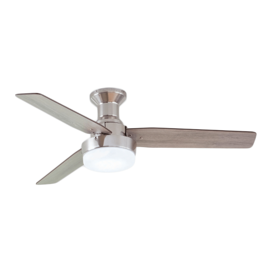
MAC CEILING FAN
1
ITEM #3025022
MODEL #42299
Español p. 18
Advertisement
Table of Contents

Related Manuals for Harbor Breeze 42299


Summary of Contents for Harbor Breeze 42299
- Page 1 ITEM #3025022 MAC CEILING FAN MODEL #42299 Español p. 18 HARBOR BREEZE and logo design are trademarks or registered trademarks of LF, LLC. All rights reserved. ATTACH YOUR RECEIPT HERE Purchase Date _________________________ Questions, problems, missing parts? Before returning to your retailer, call our customer service department at 1-888-251-1003, 8 a.m.
-
Page 2: Table Of Contents
TABLE OF CONTENTS Package Contents ..............3 Hardware Contents . -
Page 3: Package Contents
PACKAGE CONTENTS PART DESCRIPTION QUANTITY Mounting Bracket (preassembled to Canopy [B]) Canopy (preassembled to Motor Assembly [C]) Motor Assembly Fitter Plate (preassembled to Motor Assembly [C]) Fitter Plate Screw (preassembled to Fitter Plate [D]) Light Pan Light Pan Screw (preassembled to Light Pan [F]) Light Kit Glass Bowl Blade... -
Page 4: Hardware Contents
HARDWARE CONTENTS (shown actual size) Wire Connector Blade Screw Blade Washer Screw Cap Qty. 1 Qty. 9 Qty. 9 Qty. 9 + 1 extra + 1 extra + 1 extra + 1 extra... -
Page 5: Safety Information
SAFETY INFORMATION Please read and understand this entire manual before attempting to assemble, operate or install the product. • Before you begin installing the fan, disconnect the power by removing fuses or turning off the circuit breakers. • Make sure all electrical connections comply with local codes, ordinances, the National Electrical Code and ANSI/NFPA 70-199. -
Page 6: Preparation
SAFETY INFORMATION CAUTION: Be sure the outlet box is properly grounded or that a ground (green or bare) wire is present. CAUTION: Carefully check all screws, bolts and nuts on the fan motor assembly to ensure they are secured. CAUTION: This device complies with part 15 of FCC Rules. Operation is subject to the following two conditions: 1) This device may cause harmful interference, and 2) this device must accept any interference received, including interference that may cause undesired operation. -
Page 7: Initial Installation
INITIAL INSTALLATION 1. Turn off the circuit breakers and the wall switch to the fan supply line leads. DANGER: Failure to disconnect the power supply prior to installation may result in serious injury or death. 2. This fan is intended for Flushmount Installation. Standard Mounting, Angle Mounting, and Closemount installations are not available. - Page 8 INITIAL INSTALLATION 4. Loosen all four mounting bracket screws (M), then completely remove two mounting bracket screws (M) from the round holes in the canopy (B). Set them aside for later use. Remove mounting bracket (A) from canopy (B). Round Hole 5.
-
Page 9: Wiring
WIRING WARNING: To reduce the risk of fire, electrical shock or personal injury, wire connectors provided with this fan are designed to accept only one 12-gauge house wire and two lead wires from the fan. If your house wire is larger than 12-gauge and/or there is more than one house wire to connect to the two fan lead wires, consult an electrician for the proper size wire connectors to use. -
Page 10: Final Installation
FINAL INSTALLATION 1. Slide the canopy (B) over the mounting bracket (A), aligning the slotted holes in the canopy (B) with the Slotted Hole previously loosened mounting bracket screws (M) in the mounting bracket (A). Twist the canopy (B) clockwise to lock. - Page 11 FINAL INSTALLATION 4. Remove the three light pan screws (G) preassembled to the side of the light pan (F).Connect the 9-pin connector from the fan to the 9-pin connector from the light kit (H). Secure the light kit (H) with the previously removed light pan screws (G).
- Page 12 FINAL INSTALLATION 7. Remove the battery cover from the back of the remote found in remote pack (L). Insert the battery from remote pack (L) into the remote; ensure polarity of LED Indicator battery matches the polarity indicated in the battery compartment -- positive (+) to positive (+) and negative (-) to negative (-).
-
Page 13: Operating Instructions
OPERATING INSTRUCTIONS 1. To operate the fan using the remote, press and release the following buttons: 1 - High fan speed LED Indicator 2 - Medium fan speed 3 - Low fan speed 4 - Fan Power - Turns the fan off. Light Delay Off mode - Press and hold the fan power button (4) for five seconds, which will turn off light after one minute. -
Page 14: Care And Maintenance
CARE AND MAINTENANCE At least twice each year, tighten all screws on the fan. Clean the motor housing with only a soft brush or lint-free cloth to avoid scratching the finish. Clean the blades with a lint-free cloth. Total fixture wattage is 16 watts; do not attempt to replace LED. Battery Replacement: Use A23, 12-volt battery. - Page 15 TROUBLESHOOTING PROBLEM POSSIBLE CAUSE CORRECTIVE ACTION 1. The blades are loose. 1. Check and tighten all screws that hold the fan blades to the blade arms and the motor. 2. There is a cracked blade. 2. Replace the cracked blade. 3.
-
Page 16: Limited Lifetime Warranty
LIMITED LIFETIME WARRANTY The manufacturer warrants this fan to be free from defects in workmanship and materials present at time of shipment from the factory for a lifetime from the date of purchase by the original purchaser. The retailer also warrants that all other fan parts, excluding any glass or plastic blades, to be free from defects in workmanship and material at the time of shipment from the factory for a period of one year after the date of purchase by the original purchaser. -
Page 17: Replacement Parts List
REPLACEMENT PARTS LIST For replacement parts, call the customer service department at 1-888-251-1003, 8 a.m. - 8 p.m., EST, Monday - Sunday. You could also contact us at partsplus@lowes.com or visit www.lowespartsplus.com. PART DESCRIPTION PART# Mounting Bracket 4L000014460 Light Kit 4L000014470 Glass Bowl 4A166920001...
Need help?
Do you have a question about the 42299 and is the answer not in the manual?
Questions and answers