Advertisement
Table of Contents
- 1 Table of Contents
- 2 Package Contents
- 3 Hardware Contents
- 4 Safety Information
- 5 Preparation
- 6 Initial Installation
- 7 Standard or Angled Mounting Instructions
- 8 Closemount Instructions
- 9 Wiring
- 10 Final Installation
- 11 Operating Instructions
- 12 Care and Maintenance
- 13 Troubleshooting
- 14 Limited Lifetime Warranty
- 15 Replacement Parts List
- Download this manual
HARBOR BREEZE and logo design are trademarks or
registered trademarks of LF, LLC. All rights reserved.
Purchase Date _________________________
Thank you for purchasing this HARBOR BREEZE product.
Questions, problems, or missing parts?
Before returning, contact us at:
888-251-1003, 8 a.m. - 8 p.m., EST, Monday - Sunday or at ascs@lowes.com.
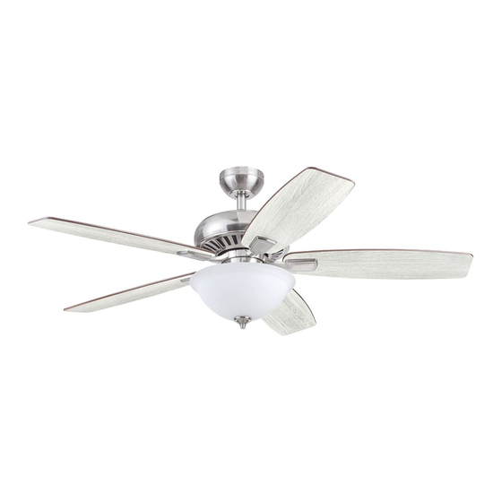
SG24548
ITEM #3856481/3856480/5737478
OXFORD CEILING FAN
ATTACH YOUR RECEIPT HERE
1
MODEL #42473/42474/43387
Español p. 24
Advertisement
Table of Contents

Related Manuals for Harbor Breeze OXFORD 42473


Summary of Contents for Harbor Breeze OXFORD 42473
- Page 1 MODEL #42473/42474/43387 OXFORD CEILING FAN Español p. 24 ATTACH YOUR RECEIPT HERE HARBOR BREEZE and logo design are trademarks or registered trademarks of LF, LLC. All rights reserved. Purchase Date _________________________ Thank you for purchasing this HARBOR BREEZE product. Questions, problems, or missing parts? Before returning, contact us at: 888-251-1003, 8 a.m.
-
Page 2: Table Of Contents
TABLE OF CONTENTS Package Contents ..............3 Hardware Contents . -
Page 3: Package Contents
PACKAGE CONTENTS PART DESCRIPTION QUANTITY Downrod Downrod Pin (preassembled to Downrod [A]) Downrod Clip (preassembled to Downrod [A]) Mounting Bracket (preassembled to Canopy [E]) Canopy Canopy Cover (preassembled to Canopy [E]) Mounting Bracket Screw (preassembled to Mounting Bracket [D]) Yoke Cover Motor Assembly Set Screw (preassembled to Motor Assembly [I]) Phillips-head Closemount Screw (preassembled to Motor Assembly [I]) -
Page 4: Hardware Contents
HARDWARE CONTENTS (shown actual size) Wire Blade Screw Blade Washer Plug Button Motor Screw Connector Qty. 15 Qty. 15 Qty. 1 1 extra Qty. 3 + 1 extra + 1 extra + 1 extra... -
Page 5: Safety Information
SAFETY INFORMATION Please read and understand this entire manual before attempting to assemble, operate, or install the product. • Before you begin installing the fan, disconnect the power by removing fuses or turning off the circuit breakers. • Make sure that all electrical connections comply with local codes, ordinances, the National Electrical Code, and ANSI/NFPA 70-199. -
Page 6: Preparation
SAFETY INFORMATION CAUTION: Read all instructions and safety information before installing your new fan. Review the accompanying assembly diagrams. CAUTION: Be sure the outlet box is properly grounded or that a ground (green or bare) wire is present. CAUTION: Carefully check all screws, bolts and nuts on the fan motor assembly to ensure they are secured. -
Page 7: Initial Installation
INITIAL INSTALLATION 1. Turn off the circuit breakers and the wall switch to the fan supply line leads. DANGER: Failure to disconnect the power supply prior to installation may result in serious injury or death. 2. Determine the mounting method to use. Standard Mounting is best suited for ceilings 8 ft. - Page 8 INITIAL INSTALLATION 4. Loosen all four mounting bracket screws (G), then completely remove the two mounting bracket screws (G) from the round holes of canopy (E). Set aside for later use. Detach mounting bracket (D) from canopy (E). 5. Attach mounting bracket (D) to outlet box (not included) using screws and washers provided with the outlet box.
-
Page 9: Standard Or Angled Mounting Instructions
STANDARD OR ANGLED MOUNTING INSTRUCTIONS 1. Remove the downrod clip (C) and downrod pin (B) from the downrod (A). Then partially loosen the set screws (J) in the yoke at the top of the motor assembly (I). 2. Insert the downrod (A) through the canopy (E) and yoke cover (H). - Page 10 STANDARD OR ANGLED MOUNTING INSTRUCTIONS 4. Depending on the length of downrod you use, you may need to cut the lead wires back to simplify the wiring. If you decide to cut back the lead wires, it is suggested that you do so in the following manner: Take the lead wires and make sure that you have pulled them all the 8 in.
-
Page 11: Closemount Instructions
CLOSEMOUNT INSTRUCTIONS Helpful Hint: The downrod (A), canopy cover (F) and yoke cover (H) are not used in this type of installation. 1. Remove the canopy cover (F) from the bottom of the canopy (E). 2. Remove three Phillips-head closemount screws (K) from the top of the motor assembly (I). -
Page 12: Wiring
WIRING WARNING: To reduce the risk of fire, electrical shock or personal injury, wire connectors provided with this fan are designed to accept only one 12-gauge house wire and two lead wires from the fan. If your house wire is larger than 12-gauge and there is more than one house wire to connect to the two fan lead wires, consult an electrician for the proper size wire connectors to use. -
Page 13: Final Installation
FINAL INSTALLATION Note: Closemount installation will not have the downrod (A), yoke cover (H) or canopy cover (F). 1. Align the canopy (E) over the loosened mounting bracket screws (G) preassembled on mounting bracket (D). Place the keyholes of the canopy (E) onto the mounting bracket screws (G) and rotate the canopy (E) clockwise. - Page 14 FINAL INSTALLATION 3. Partially insert three blade screws (BB) along with three blade washers (CC) through one blade (W) and into one blade arm (V). Tighten each blade screw (BB) with a Phillips screwdriver (not included), starting with the one in the middle.
- Page 15 FINAL INSTALLATION 6. Secure the switch housing (O) along with light kit (P) to the fitter plate (L) using the previously removed fitter plate screws (M). 7. Install bulbs (Y) into the sockets of the light kit (P). Important: Make sure to allow the bulbs (Y) and light kit (P) to cool before you replace the bulbs.
- Page 16 FINAL INSTALLATION 9. Secure glass bowl (X) with rubber washer (R) and hex nut (Q). Then attach finial cap (S) and finial (T). 10. To install the fan without the light kit (P), remove Hex Nut the hex nut and lock washer from the rod on the Lock Washer inside of the switch housing cap (O).
- Page 17 FINAL INSTALLATION 12. If you wish to install the wall bracket from remote pack (U), choose desired location and insert screws from remote pack (U) into holes of wall bracket and into installation site. Store the remote from remote pack (U) Mounting on the wall bracket by placing the slot on the back of Bracket...
-
Page 18: Operating Instructions
OPERATING INSTRUCTIONS 1. Remove the battery cover from the back of the remote Remote found in remote pack (U). Insert the battery from remote pack (U) into the remote; ensuring the polarity of the LED Indicator battery matches the polarity indicated in the battery compartment -- positive (+) to positive (+) and negative (-) to negative (-). - Page 19 OPERATING INSTRUCTIONS 3. Using a ceiling fan will allow you to raise your thermostat setting in summer and lower your thermostat setting in winter without feeling a difference in your Reverse comfort. Switch In warmer weather, push the reverse switch left to display a sun icon, which will result in downward airflow creating a wind chill effect (Fig.
-
Page 20: Care And Maintenance
CARE AND MAINTENANCE At least twice each year, lower the canopy to check the downrod assembly, and then tighten all screws on the fan. Clean the motor housing with only a soft brush or lint-free cloth to avoid scratching the finish. Clean the blades with a lint-free cloth. Bulb Replacement: Use 60-watt max. - Page 21 TROUBLESHOOTING PROBLEM POSSIBLE CAUSE CORRECTIVE ACTION 1. The blades and/or blade are 1. Check and tighten all screws that hold loose. the fan blades to the blade arms and the blade arms to the motor. 2. The blades are unbalanced. 2.
-
Page 22: Limited Lifetime Warranty
LIMITED LIFETIME WARRANTY Set forth below, the manufacturer warrants the fan motor for this ceiling fan to be free from defects in workmanship and material for the life of the product. Also, subject to the limitations below, the manufacturer warrants all ceiling fan parts (“ceiling fan parts” excludes the motor and parts made in whole or in part with glass) to be free from defects in workmanship and material for a period of one year after the date of purchase by the original purchaser at retail. -
Page 23: Replacement Parts List
REPLACEMENT PARTS LIST For replacement parts, call the customer service department at 888-251-1003, 8 a.m. - 8 p.m., EST, Monday - Sunday. You could also contact us at ascs@lowes.com. PART DESCRIPTION #3856481 #3856480 #5737478 Downrod 4L000005220 4L000015470 4L000018960 Mounting Bracket 4L000006410 4L000006350 4L000006350...
Need help?
Do you have a question about the OXFORD 42473 and is the answer not in the manual?
Questions and answers
can this **** be operated by a hard wired wall switch in addition to the remote
Yes, the Harbor Breeze OXFORD 42473 ceiling fan can be operated by a hard wired wall switch, but the power supply to the fan must be controlled by the wall switch (as indicated in the installation instructions). However, fan speed and light functions are controlled by the remote, not a full-range dimmer switch.
This answer is automatically generated