Table of Contents
Advertisement
Advertisement
Table of Contents

Related Manuals for WÄRTSILÄ JOVYTEC P Series


Summary of Contents for WÄRTSILÄ JOVYTEC P Series
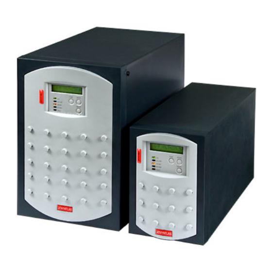
- Page 1 Operating Manual Wärtsilä JOVYTEC P 700VA – 3kVA BAX 3345...
- Page 2 Index Date Name Revision 2014-06-20 Chr. Fechteler 14/375 2014-10-29 Chr. Fechteler 14/600 2017-08-14 D. Busboom 17/262 Wärtsilä JOVYTEC P 700VA – 3kVA BAX 3345 - 2 -...
- Page 3 N O T E S ! Notes concerning this operating manual Thank you for deciding to purchase this uninterrupted power supply units (UPS) out of the series JOVYTEC P. It represents reliable protection for the attached consumers. Please read through this manual very carefully This manual contains regulations covering safety, installation and operating methods which will help you guarantee to obtain the full performance und operational readiness which the UPS can offer.
-
Page 4: Table Of Contents
TABLE OF CONTENT GENERAL NOTES DESCRIPTION OF THE SYSTEM GENERAL DESCRIPTION OF THE FUNCTION TECHNICAL DATA DIMENSIONS AND VIEWS JOVYTEC P 700 – P 1500 REAR VIEW JOVYTEC P 700 – P 1000 REAR VIEW JOVYTEC P 1500 JOVYTEC P 2000 – P 3000 REAR VIEW JOVYTEC P 2000 –... - Page 5 ASSIGNMENT OF THE RS232 INTERFACE USB PORT (OPTIONAL) SPECIAL EQUIPMENT 10.1 ELECTRONIC STOP FUNCTION MANUAL BYPASS (OPTIONAL) RELAY CARD (OPTIONAL) 13.1 TECHNICAL DATA / AUTONOMY TIMES 13.2 VIEWS 13.2.1 BATTERY CABINET B10 - B12 13.2.2 BATTERY CABINET BM1 13.2.3 BATTERY CABINET BM2 13.2.4 BATTERY CABINET BM3 13.3...
-
Page 6: General Notes
General notes N O T E! The UPS should be attached to the mains supply and switched on at the latest 4 weeks after receipt in order to prevent the battery discharging itself. P L E A S E N O T E! The batteries used are just designed for the required bridging time to meet the nominal load of the UPS. -
Page 7: General Description Of The Function
General description of the function Normal operation During normal operation the battery and the inverter are supplied with power via a rectifier (online operation). The change-over from alternating voltage to direct voltage and back to alternating voltage again is achieved by a sinusoid output voltage with a low distortion factor. - Page 8 Fault in the inverter or an overload (bypass operation) In the case of a fault occurring in the inverter or an overload, a switch-over device switches the load back to the mains. This means that, in the case of a power failure, the connected consumers will no longer be supplied with power.
-
Page 9: Technical Data
Technical data JOVYTEC P 700 cos 0,7 ind. Output power 700VA / 490W 230V Input voltage ranges Voltage 168V - 276V (0-100% load) 140 - 159V (0-70% load) 120 - 139V (0-40% load) Current with standard charger Network supply Current with additional charger 3,9A Frequency... - Page 10 JOVYTEC P 1000 cos 0,7 ind. Output power 1000VA / 700W 230V Input voltage ranges Voltage 168V - 276V (0-100% load) 140 - 159V (0-70% load) 120 - 139V (0-40% load) Current with standard charger Network supply Current with additional charger 5,2A Frequency 50Hz ±3Hz or 60Hz ±3Hz...
- Page 11 JOVYTEC P 1500 cos 0,7 ind. Output power 1500VA / 1050W 230V Input voltage ranges Voltage 168V - 276V (0-100% load) 140 - 159V (0-70% load) 120 - 139V (0-40% load) Current with standard charger 5,7A Network supply Current with additional charger 6,9A Frequency 50Hz ±3Hz or 60Hz ±3Hz...
- Page 12 JOVYTEC P 2000 cos 0,7 ind. Output power 2000VA / 1400W 230V Input voltage ranges Voltage 168V - 276V (0-100% load) 140 - 159V (0-70% load) 120 - 139V (0-40% load) Current with standard charger 7,7A Network supply Current with additional charger 10,1A Frequency 50Hz ±3Hz or 60Hz ±3Hz...
- Page 13 JOVYTEC P 3000 cos 0,7 ind. Output power 3000VA / 2100W 230V Input voltage ranges Voltage 168V - 276V (0-100% load) 140 - 159V (0-70% load) 120 - 139V (0-40% load) Current with standard charger Network supply Current with additional charger 14,4A Frequency 50Hz ±3Hz or 60Hz ±3Hz...
-
Page 14: Dimensions And Views
Dimensions and views JOVYTEC P 700 – P 1500 Wärtsilä JOVYTEC P 700VA – 3kVA BAX 3345 - 14 -... -
Page 15: Rear View Jovytec P 700 - P 1000
Rear view JOVYTEC P 700 – P 1000 Electronic - Stop RS232 - Interface Relay Card TAE – Protection Circuit USB – Interface (option) Connector for external Battery Load output socket Input Fuse Mains Input Plug Cold output socket for consumers Wärtsilä... -
Page 16: Rear View Jovytec P 1500
Rear view JOVYTEC P 1500 Electronic - Stop RS 232 - Interface TAE – Protection Circuit Relay Card USB – Interface (option) Connector for external Input Fuse Battery Main Input Plug Load Output Sockets Wärtsilä JOVYTEC P 700VA – 3kVA BAX 3345 - 16 -... -
Page 17: Jovytec P 2000 - P 3000
JOVYTEC P 2000 – P 3000 Wärtsilä JOVYTEC P 700VA – 3kVA BAX 3345 - 17 -... -
Page 18: Rear View Jovytec P 2000 - P 3000
Rear view JOVYTEC P 2000 – P 3000 Mains Input Plug Electronic - Stop Input Fuse Electronic - Stop RS232 - Interface TAE – Protection Circuit Relay Card USB – Interface (option) Connector for external Battery Output Fuses Cold Output Socket for Load Load Output Sockets Wärtsilä... -
Page 19: Electrical Connection
Electrical connection P L E A S E N O T E Only trained personnel are allowed to work on the UPS unit. Observe all corresponding safety regulations. Marking of cables is to be according to DIN EN 60445! When connecting to the UPS unit, ensure use of an adequately sized protective- conductor connection! P L E A S E N O T E When working on the batteries it is possible for dangerous situations to arise... -
Page 20: Commissioning
Commissioning P L E A S E N OT E! The unit should be started over the input mains. If the input mains is not available for a short time then it is also possible to start the unit over the external battery. It is a basic prerequisite for this operating mode that the UPS unit was one time operated over the energy supplier’s mains network. -
Page 21: Operating And Indicating Elements
Operating and indicating elements LED and function keys Display indicator The display indicator informs about the operating modes, menu points and parameters. ON/OFF button The UPS unit can be switched on and off using the ON/OFF button. The formalism is as follows: The UPS unit is switched on by pressing the ON/OFF button for about 3 seconds. -
Page 22: Parameters
Parameters Indicator Function of the indicator O/P VOLT = 230.0V Output voltage of the UPS O/P FREQ = 50,0Hz Output frequency of the UPS I/P VOLT = 230,2V Input voltage of the UPS I/P FREQ = 50,2Hz Input frequency of the UPS BAT VOLT = 24V Battery voltage of the battery pack O/P LOAD% = 80%... -
Page 23: Table Of The Adjustable Parameters
Table of the adjustable parameters Selections Adjustable Indication in Factory Explanation parameter the display setting parameter 208/220/ Adjusting the output voltage O/P V adjustment Nominal voltage 230V 230/240V ± 2% Setting the Frequency tolerance in I/P Freq. Adjustment ± 5% ±... -
Page 24: Offline Mode
OFFLINE mode The UPS unit can be operated using special settings via the display or with the software supplied in offline mode. This operating mode has the advantage of only using a small amount of energy. The formalism for setting to OFFLINE mode is as follows: - The key FUNC must be pressed for 2 seconds to obtain configuration mode. -
Page 25: Free Running On, Bypass Activated
Bypass lower limit: 230 V x (1-0.2) = 230 V x 0.8 = 184 V bypass upper limit: 230 V x (1+0.15) = 230 V x 1.15 = 264.5 V A +/-2% tolerance was selected for the input frequency so the narrow input frequency window is as follows: Input frequency lower limit: 50Hz x (1-0.02) = 49Hz Input frequency upper limit: 50Hz x (1+0.02) = 51Hz The broader input frequency range covers the range of 45Hz - 65Hz. -
Page 26: Generator Mode
7.7.6 Generator mode Generator mode (adjustable via the panel) ensures that the UPS unit is not constantly switching over to battery operation, since the output voltage of the generator often demonstrates distortions or irruptions, but remains in online mode and thus a sinusoidal output voltage for the consumers is achieved. This functionality has a low loading effect on the battery which means that the working life of the battery is maintained. -
Page 27: Service Information
Service information S E R V I C E – H O T L I N E ! Telefon: 04958 - 9394 - 30 Telefax: 04958 - 9394 - 10 E-Mail: service.jovyatlas.de@wartsila.com Internet: http://www.jovyatlas.de Remote monitoring The UPS unit is fitted as standard with an RS 232 signal output. This signal output is designed as a RS232- interface (SUB-D, 9-pin), and there is optionally the possibility of using an additional USB interface. -
Page 28: Usb Port (Optional)
USB port (optional) Connection of the UPS to a computer is also possible via the USB interface at the rear of the UPS unit. If the USB interface is to be used then simultaneous use of the RS 232 interface is not possible. Communication between the UPS and the computer takes place via a conventional USB connection cable (PC: plug -A / UPS unit: plug -B) and can only be used with the software “UPSMON“... -
Page 29: Relay Card (Optional)
Relay card (optional) There is also the option to fit the UPS unit with a relay card (optional). This relay card provide voltage-free contacts for external further use. These contacts are designed a standard as closing contacts, that is they close in the case of a fault. There is also a possibility of designing these contacts as opening contacts by reversing a jumper on the relay card. - Page 30 Wärtsilä JOVYTEC P 700VA – 3kVA BAX 3345 - 30 -...
-
Page 31: Technical Data / Autonomy Times
Battery Cabinets 13.1 Technical Data / Autonomy Times For longer autonomy of ups systems are additional battery cabinets necessary. The available cabinets for the ups systems are described in the following table: Time Battery Dimensions Battery Cabinet UPS and Battery Cabinet [min] Cabinet W x H x D [mm]... -
Page 32: Views
13.2 Views 13.2.1 Battery Cabinet B10 - B12 Dimensions (apporx., in mm) Battery Cabinet Weight without Type: Batteries (in kg) 1090 1340 1620 1) Only at Battery Cabinet B12 Wärtsilä JOVYTEC P 700VA – 3kVA BAX 3345 - 32 -... -
Page 33: Battery Cabinet Bm1
13.2.2 Battery Cabinet BM1 Battery Cable to UPS - System BATTERIE F1 F2 ZWISCHEN- KREISSPANNUNG Battery Fuses F1/F2 Plastic Feet 13.2.3 Battery Cabinet BM2 Battery Cable to UPS - System BATTERIE F1 F2 ZWISCHEN- KREISSPANNUNG Battery Fuses F1/F2 Plastic Feet 13.2.4 Battery Cabinet BM3 Battery Fuses F1/F2... -
Page 34: Connection
13.3 Connection 13.3.1 Battery Cabinets B10/B11/B12 Battery Fuses Battery- terminals Wärtsilä JOVYTEC P 700VA – 3kVA BAX 3345 - 34 -... -
Page 35: Battery Cabinet Bm1 - Bm3
Battery Cabinet BM1 – BM3 13.3.2 These battery cabinets are fit up with flexible connection wires. At the rear of the battery cabinets are two fuses of the battery reachable (F1:positive pole, F2: negative pole). Battery Fuses UPS Device JOVYTEC P 700 35A DO2 35A DO2 JOVYTEC P 1000... -
Page 36: 13.4 Battery Operation
13.4 Battery operation In the case of a network failure the consumers are supplied without interruption from the battery. In battery operation the LED ON-BAT (Battery operation) lights up and an acoustic warning tone sounds every 5 seconds. The acoustic warning tone changes towards the end of the bridging time, that is when the battery is virtually discharged, to two bleeps sounding every 5 seconds. -
Page 37: Replacing An Internal Ups Battery
Replacing an internal UPS battery UPS units of the type JOVYTEC P offer the option of replacing the battery while operating. One must ensure in this case that the UPS unit is running in normal mode and not in autonomy mode. Proceed as follows to replace the battery: Remove the display panel through the stripping of the plastic cover. -
Page 38: Notes
Notes ______________________________________________________________________________________ ______________________________________________________________________________________ ______________________________________________________________________________________ ______________________________________________________________________________________ ______________________________________________________________________________________ ______________________________________________________________________________________ ______________________________________________________________________________________ ______________________________________________________________________________________ ______________________________________________________________________________________ ______________________________________________________________________________________ ______________________________________________________________________________________ ______________________________________________________________________________________ ______________________________________________________________________________________ ______________________________________________________________________________________ ______________________________________________________________________________________ ______________________________________________________________________________________ ______________________________________________________________________________________ ______________________________________________________________________________________ ______________________________________________________________________________________ Wärtsilä JOVYTEC P 700VA – 3kVA BAX 3345 - 38 -...
Need help?
Do you have a question about the JOVYTEC P Series and is the answer not in the manual?
Questions and answers