Table of Contents
Advertisement
Advertisement
Table of Contents
Troubleshooting

Related Manuals for WÄRTSILÄ JOVYSTAR-DELTA


Summary of Contents for WÄRTSILÄ JOVYSTAR-DELTA
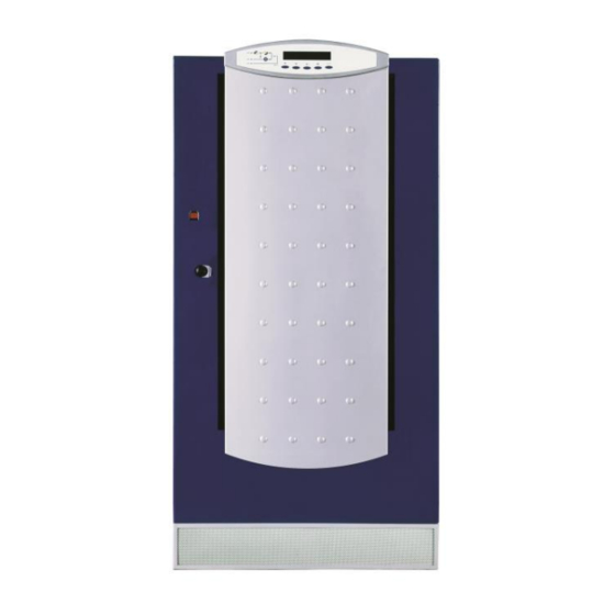
- Page 1 Operating manual Wärtsilä JOVYSTAR – DELTA 40 – 150kVA BAX 4647E...
- Page 2 Index Date Name Status 2014-06-17 D. Busboom First Edition 2014-06-25 D. Busboom 14/392 2017-02-20 D. Busboom 17/063 Important Notice Read this operating manual carefully This operating manual consists of safety-rules and rules for installation and operation as well, to help you to maximize your benefit on this product.
-
Page 3: Table Of Contents
Table Of Contents Technical Data General Notes Description Of The System Why Using A UPS? General Description of A UPS Installation Reception Transport Electrical Connection Operation Setting Up Shut-down Procedure Parallel Redundant System Start Parallel Redundant System Stop Manual Bypass Front Panel Options Temperature Compensation... -
Page 4: Technical Data
Technical Data Wärtsilä JOVYSTAR DELTA Online UPS-Type 40 kVA 60 kVA 80 kVA Output Output apparent power (cos φ = 0,8) 40 kVA 60 kVA 80 kVA Output active power (cos φ = 1) 32 kW 48 kW 64 kW Rated output voltage 3 x 400/230 V - Tolerance static, symmetric load... - Page 5 Wärtsilä JOVYSTAR DELTA Online UPS-Type 100 kVA 125 kVA 150 kVA Output Output apparent power (cos φ = 0,8) 100 kVA 125 kVA 150 kVA Output active power (cos φ = 1) 80 kW 100 kW 120 kW Rated output voltage 3 x 400/230 V - Tolerance static, symmetric load ±1 %...
-
Page 6: General Notes
General Notes It is mandatory to fulfil al works and safety requirements according to rules and instructions described herein for protect- ing the personnel working at the UPS as well as maintaining optimal duty-cycles of the UPS. All personnel installing/de- installing, starting up, and maintaining the unit must be familiar with and observe these safety regulations. -
Page 7: Description Of The System
Description Of The System Congratulations for chosen a UPS out of the JOVYSTAR series! This type of static UPS incorporates the latest state of technology in power electronics and digital signal processing. The UPS offers the optimal solution for problems in power supply of computer-systems. -
Page 8: General Description Of A Ups
- Prevention from frequency variations, - Low noise, - Small, compact design, - Remote control facility by PC (option), - Remote control by modem (option). General Description of A UPS UPS of this series are true on-line, double conversion UPS (classification-code VFI-SS-111); the inverter supplies the load under normal operating conditions, whether mains is available or not (according to the battery autonomy time). - Page 9 ectifier The rectifier converts the input AC-voltage into a regulated DC-voltage supplying the inverter and charging the batteries. - Inverter The inverter converts the DC-voltage delivered by the rectifier or by the battery into an AC-voltage, regulated by Pulse-Width-Modulation. The output of the inverter is short circuit proof by electronic short-circuit-protection.
- Page 10 2.3.3 Battery and Battery Charger The battery is placed inside the UPS up to 32KVA in case of small autonomy times. It is placed in an external battery cabinet for higher UPS ratings and/or autonomy times. The control-electronic for the rectifier includes the circuits for the battery charger too.
- Page 11 2.3.7.3 Rectifier- Or Mains Failure The inverter is supplied by the battery for the autonomy time specified by the battery. The load is supplied directly by the inverter via the static switch. MBCB (Manual bypass) (Manueller Bypass) SBCB (Rectifier) (Inverter) (Gleichrichter) (Wechselrichter) Mains...
-
Page 12: Installation
Installation Reception After reception of the UPS, unpack immediately and carry-out an accurate visual check for any transport-damages. IMPORTANT: In case of objections relating to damage incurred during transport these must be immediately notified to the transportation company after reception of the product. When the UPS is not installed immediately it must be stored carefully in vertical position, as indicated on the packing and conserved in a dry and sheltered room in its box so that it is protected from dust. -
Page 13: Electrical Connection
3.2.3 Dimensions And Wall System Distance Additional cabinet Additional cabinet (12 pulse rectifier) (12 pulse rectifier) Additional cabinet Dimensions and wall system distance (12 pulse rectifier) Designation 40-60kVA | 80-150kVA L – mm | 815 P – mm | 825 H –... - Page 14 ATTENTION: The input lines to the UPS must be fuse protected. The use of residual current switches in the line sup- plying the UPS is not recommended. The leakage current due to the RFI filters is rather high and it can cause spurious tripping of the protection device.
- Page 15 80-150 kVA (Bars with mounting hole) Battery Fuse monitoring Rectifier input Bypass input Output (option) 2-L1 2-L2 2-L3 3-L1 3-L2 3-L3 1-L1 1-L2 1-L3 Note.: L1-L3 and N = Hole for screw M10. PE Terminal: Bolt M10 3.3.2 External Battery IMPORTANT: Prior to connecting to any external battery the standard EN62040, par.
- Page 16 3.3.2.2 Battery Connection in Internal Battery Shelf BOTTOM BATTERY DRAWER NO. REAR TO BCB FRONT Battery connection in internal battery shelf Wärtsilä JOVYSTAR – DELTA 40 – 150kVA BAX 4647E - 16 -...
-
Page 17: Operation
Operation Prior to carrying out whatever procedure described in this chapter, read carefully the instructions, in order to avoid pos- sible damages to persons or the UPS due to wrong maneuvers. Setting Up NOTE: The battery circuit breaker BCB may be switched only when the rectifier is running. Otherwise the rectifier could be damaged. -
Page 18: Parallel Redundant System Start
CAUTION: Even at switched off input mains, a dangerous high voltage is still present inside the UPS! CAUTION: The circuit breaker in the external battery cabinet may only be operated without current flow. Observe the switch off procedure! The load on the output of the UPS has to be switched off prior to operating the battery circuit breaker. - Page 19 CAUTION: Even at switched off input mains, a dangerous high voltage is still present inside the UPS! NOTE: The load is powered now by the mains. Any blackout in the mains will lead to a blackout for the loads. 4.5.2 Manual Bypass (Parallel Redundant Operation) Initiation The procedure must be carried out at every UPS unit: Set the service switch into Bypass position, wait and acknowledge the alarm as described for a single UPS...
-
Page 20: Front Panel
Front Panel The front panel of a UPS consists of a double row alphanumeric display plus 5 function keys. It allows the complete monitoring of the UPS status. The mimic flow helps to understand the operating status of the UPS. JOVYATLAS RESET 4.6.1... - Page 21 4.6.2 Menu Structure Operation of the UPS is menu-oriented. The menu is hierarchical, the individual sub-menus can be entered by using the function keys of the panel. <NAME> XXX kVA XXX YYY ZZZ Volt <NAME> XXX kVA MEASURES <NAME> XXX kVA <NAME>...
- Page 22 4.6.3 Single Display Items The default screen appears on the LCD while the UPS is in normal operation <NAME> xxx KVA (with no alarm present); it shows the name of the UPS, the nominal power Vout = XXX Volt and the nominal output voltage. Pressing a key the main menu, with all the functions and parameters, is accessed.
- Page 23 DC measured values. It is accessed pressing the key, pressing the <NAME> xxx KVA keys scrolls to the other menu items. AC / DC BATTERY measured values. It is accessed pressing the key, pressing <NAME> xxx KVA the keys scrolls to the other menu items. BATTERY Pressing the key the main menu screen is shown, pressing the keys...
- Page 24 4.6.4.1.2 Bypass Pressing the key the following parameter is shown, while the key BYPASS VOLTAGE leads to the previous display. XXX YYY ZZZ Volt Pressing the key the following parameter is shown, while the key BYPASS FREQUENCY leads to the previous display. XX Hertz Pressing the key leads to the MEASURES main menu, pressing the...
- Page 25 4.6.4.1.5 Battery Pressing the key the following parameter is shown, while the key BATTERY VOLTAGE leads to the previous display. XXX Vdc Pressing the key the following parameter is shown, while the key BATTERY TYPE leads to the previous display. XXX Ah Pressing the key the following parameter is shown, while the key...
- Page 26 Pressing the key the returns to main menu, pressing the keys <NAME> xxx KVA the other sub-menus are coming up. EXIT 4.6.4.2.1 UPS Status Pressing the key the status and/or any pending alarms of the UPS are UPS STATUS shown, while the key leads to the previous display.
- Page 27 The first alarm shown is the most recent in order of time; every new alarm makes all the alarms within that list shift one position, clearing the oldest event. For each event is shown the alarm code, the date and time; an asterisk next to the code indicates that the alarm has cleared at the date and time indicated.
- Page 28 Password entering; if wrong the main menu screen is shown. The password PASSWORD is “123”, it is unchangeable. It shall notice the operator that deeper impacts are going to be done. Reset status of the UPS. It is used in case of a blocked retransfer. It is ac- SPECIAL MENU cessed pressing the key, pressing the keys...
-
Page 29: Options
4.6.4.3.4 Battery Test The BATTERY TEST cannot be started if the dip switch on the P card in “off” position. Pressing the key RESET the battery test is started. Pressing the key PRESS RESET leads to the special menu. TO START TEST Options Temperature Compensation With this option the charging voltage for the battery can by regulated by means of the temperature. -
Page 30: Battery Symmetry Monitoring
5.2.2 System Layouts The parallel redundant system has better static and dynamic performances in comparison to a single unit since, owing to the redundancy, the total amount of power available his higher than the nominal load of the overall system. Overload The overload limit of a parallel redundant system depends on the number of the units which are connected to the load: Imax = n x In, where “n”... -
Page 31: Remote Operating Panel
Remote Operating Panel A UPS can be monitored remotely with a remote panel for a distance up to 400m; it can be installed in a control room, and provides the same user interface as the local panel. NOTE: Please make sure that 220V-240V, 50/60Hz power supply is available for the remote panel. The remote operating panel is connected to the RS-485 of the UPS by a shielded cable 4 x 0,5mm, of 400m maximum length and two DB9 connectors. -
Page 32: Shut-Down Software
Shut-down Software A controlled shutdown of computer-systems which are being attached to the UPS is possible by using a shutdown- software. Using this option either the relay-PCB, a SNMP-adaptor or a direct connection between the PC and the serial interface is necessary. The shutdown software is available for various operating systems. Please contact our sales department for further details. -
Page 33: Functional Test
Functional Test The functional test of the UPS should be performed every six months and include the following tasks: Activate the manual bypass according to chapter 4 of this manual. Disconnect the UPS according to chapter 4 of this manual and check display and LED’s when restarting the system as well as : Correct start of the rectifier and inverter, Function of the static switch,... -
Page 34: Troubleshooting
Battery lifetime The lifetime of sealed lead-acid batteries decreases by operation at higher temperatures than +20°C. The following table shows the lifetime reduction at given temperatures. Three types of batteries with a given lifetime specified at +20°C are shown: Temperature Type A Type B (Nominal lifetime 10-12 years) - Page 35 Fault signal Description Fault correction In case of this alarm check the battery (connection, status of the cells, voltage and so on). After you have solved the BATTERY FAULT Test of the battery has failed (see A11 Battery test). problem you must go in the special menu and reset the UPS to clear the alarm.
-
Page 36: Customer Service
Properties by troubles WARNING: Please contact our Service department after a failure. Jovyatlas does not take over any liability for late error reports. Customer service NOTE: When ordering spare parts always the designation (position/component) and unit number shall be stated. Our customer service department will be pleased to send you a complete spare part list for your UPS upon request. -
Page 37: Spare Parts
Spare parts Despite employment of non-wearing components, we recommend stocking the spare parts listed below to ensure con- stant operational readiness of your UPS: Mounted Code Description Type Quantity LEVEL 1 FN001_6.3X32 AUXILIARY FUSES FB1-FB2 PB001 FN004__GGX38 FANS FUSES STATIC BYPASS FN315URB SBCB F1-F2-F3 POWER FUSES... - Page 38 IGBT INVERTER POWER IGD400A12V01 2A1 PS1-2-3-4-5-6 BRIDGE IGBT INVERTER POWER IGD700A12V01 2A1 PS1-2-3-4-5-6 BRIDGE IGBT INVERTER POWER IGD910A12V01 2A1 PS1-2-3-4-5-6 BRIDGE INVERTER STAT.SWITCH SCRD56A12V 2A3 PS4-PS5-PS6 THYRISTORS INVERTER STAT.SWITCH SCRD91A12V 2A3 PS4-PS5-PS6 THYRISTORS INVERTER STAT.SWITCH SCRD323A12V 2A3 PS4-PS5-PS6 THYRISTORS BYPASS STAT.SWITCH SCRD91A12V 2A3 PS7-PS8-PS9 THYRISTORS...
-
Page 39: Appendix
Appendix 10.1 Dimensional Drawings C o n t e n t s D r a w i n g - n o . Battery cabinets, types B10…B13 Y89 010 00 . MZ3 Battery cabinets, type B11E Y00 104 00 . MZ3 / Y00 104 01 . MZ3 10.2 Circuit Diagrams C o n t e n t s... -
Page 40: Notes
Notes ______________________________________________________________________________________ ______________________________________________________________________________________ ______________________________________________________________________________________ ______________________________________________________________________________________ ______________________________________________________________________________________ ______________________________________________________________________________________ ______________________________________________________________________________________ ______________________________________________________________________________________ ______________________________________________________________________________________ ______________________________________________________________________________________ ______________________________________________________________________________________ ______________________________________________________________________________________ ______________________________________________________________________________________ ______________________________________________________________________________________ ______________________________________________________________________________________ ______________________________________________________________________________________ ______________________________________________________________________________________ ______________________________________________________________________________________ ______________________________________________________________________________________ ______________________________________________________________________________________ Wärtsilä JOVYSTAR – DELTA 40 – 150kVA BAX 4647E - 40 -...
Need help?
Do you have a question about the JOVYSTAR-DELTA and is the answer not in the manual?
Questions and answers