Edwards EDS 200 Instruction Manual
Industrial dry vacuum pumps
Hide thumbs
Also See for EDS 200:
- Instruction manual (18 pages) ,
- Instruction manual (22 pages) ,
- Instruction manual (12 pages)

Subscribe to Our Youtube Channel
Related Manuals for Edwards EDS 200


Summary of Contents for Edwards EDS 200
- Page 1 Industrial Dry Vacuum Pumps EDS 200 AND EDS 300 INSTRUCTION MANUAL Original Instructions A41802880_C 300767970_002_C2...
- Page 2 Copyright notice ©Edwards Limited 2019. All rights reserved. Trademark credit Edwards and the Edwards logo are trademarks of Edwards Limited, Innovation Drive, Burgess Hill, West Sussex RH15 9TW. Page 2...
-
Page 3: Table Of Contents
Contents 1. Safety and compliance........6 1.1 Definition of Warnings and Cautions. - Page 4 7.6.3 Pump body thermal snap switch....... . 34 7.6.4 Grounding..........34 7.6.5 Check the direction of rotation of the motor.
- Page 5 Figure 2: Pumping speed curves EDS 200 and EDS 300....... .
-
Page 6: Safety And Compliance
A41802880_C - Safety and compliance 1. Safety and compliance 1.1 Definition of Warnings and Cautions NOTICE: Obligation to Provide Information Read and follow these instructions carefully before installing and commissioning to ensure optimum and safe operation right from the start. Safe and proper operation is guaranteed when used correctly and in accordance with the instructions contained in these operating instructions. - Page 7 A41802880_C - Safety and compliance General warning sign Warning of counter-rotating rollers Warning of automatic start-up Warning of danger of slipping Warning of electrical voltage Warning of hot surface Warning of explosion Page 7...
-
Page 8: Important Safety Information
A41802880_C - Important safety information 2. Important safety information 2.1 Mechanical hazards CAUTION: LOSS OF STABILITY DURING TRANSPORT Uncontrolled movement due to incorrect attachment / lifting / carrying / rolling or movement of the vacuum pump. Only use the attachment points and conveying means described in this manual for vertical and horizontal conveying. -
Page 9: Electrical Hazards
A41802880_C - Important safety information WARNING: UNEXPECTED RESTART Failure or malfunction of the central control system (unexpected start-up) or danger of a pump restarting automatically after switching off due to a fault. Risk of crushing, cutting or cutting off by touching moving parts due to recurring start command or power supply. -
Page 10: Thermal Hazards
A41802880_C - Important safety information DANGER: LIGHTNING STRIKE Risk of fire and injury from lightning strike. The operator is responsible for assessing the hazard potential when used outside of buildings. 2.3 Thermal hazards CAUTION: HOT SURFACES Burning of fingers, hands or arms on hot surfaces. Handle the pump only when ventilated and cooled down. -
Page 11: Noise Hazard
A41802880_C - Important safety information 2.6 Noise hazard CAUTION: HIGH NOISE LEVELS The operating conditions can cause higher noise levels than specified in the technical data. Take suitable hearing protection measures. Pressure values in bar or mbar are absolute pressures, unless expressly stated otherwise (e.g. -
Page 12: Atex Certification
The use of seal purges and correct warm-up and shut-down procedures are necessary to prevent the formation of condensation. If in any doubt, please consult Edwards. Shaft-seal purge must be maintained in order to ensure long term reliability of shaft-seals and the zoning/protection concept. -
Page 13: Conditions Of Safe Use
ATEX Directive 2014/34/EU regarding the equipment group and category and they must be applicable for use in explosive atmospheres of the respective gas group and temperature class. Accessories and additional parts should be approved by Edwards otherwise they may have a detrimental effect on the pump performance and safety. -
Page 14: Design
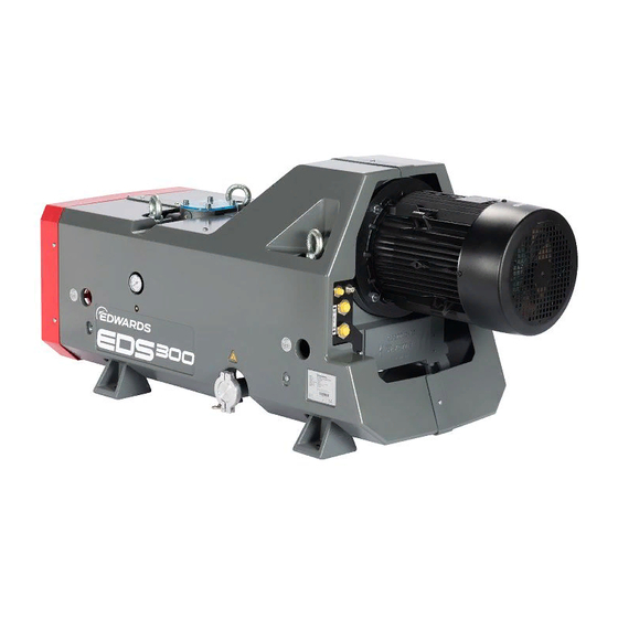
EDS 200 and EDS 300 look the same, they differ only in their performance. A. EDS 200/300 water-cooled A. EDS 200/300 water-cooled B. EDS 200/300 air-cooled (with heat exchanger) B. EDS 200/300 air-cooled (with heat exchanger) 4.1 Design The EDS dry pump range has been developed to meet the demanding requirements for pumping solutions in industrial and chemical applications. -
Page 15: Supplied Equipment
Table 2 Pumps ordering information ATEX Electrical Supply Part No. 200/400 V 50 Hz A41820945 230/460 V 60 Hz A41820946 EDS 200 water cooled 200 V 50 Hz A41820934 200/380 V 60 Hz A41820936 575 V 60 Hz A41820957 200/400 V 50 Hz... -
Page 16: Accessories
4.3.2 Accessories Table 3 Accessories Accessories Part number Exhaust pressure transmitter (PS1) A41894000 Exhaust gas temperature transmitter (TS3) A41895001 Stator temperature transmitter (Pt 100) A41895000 Roots adapter A41893000 Ultragrade® Endurance Extend 110, 1 l H11032010 Ultragrade® Endurance Extend 110, 4 l H11032012 Roots adapter for EH 500 A41893001... -
Page 17: Technical Data
A41802880_C - Technical data 5. Technical data Table 4 Technical data Pumping speed without gas-ballast > 210 m > 280 m Ultimate partial pressure < 0.05 mbar < 0.01 mbar Maximum permissible inlet pressure 1013 mbar Max. permanent discharge pressure 1200 mbar (absolute pressure) Swept volume maximum pressure rating... - Page 18 A41802880_C - Technical data Short circuit current rating according IEC/EN 60947 suitable for motors with 225 A efficiency class IE3. Second protective earth (ground) Must be fitted with cross-sectional area at least equal to conductor phase conductor size Cooling fan for heat exchanger Supply voltage 1-phase 24 V DC Nominal current consumption...
-
Page 19: Figure 2 Pumping Speed Curves Eds 200 And Eds 300
1 hour can cause damage to the pump due to a lack of lubrication. **bar(g): bar (gauge) is the overpressure, i.e. atmospheric pressure = 0 bar(g) Figure 2 Pumping speed curves EDS 200 and EDS 300 Page 19... -
Page 20: Transport And Storage
A41802880_C - Transport and storage 6. Transport and storage CAUTION: LOSS OF STABILITY DURING TRANSPORT Uncontrolled movement due to faulty attaching/lifting/carrying/rolling or moving the vacuum pump. For vertical and horizontal transport, use only the attachment points and transport means described in this manual. NOTICE: The pumps are supplied filled with synthetic oil. - Page 21 A41802880_C - Transport and storage Temperature (only for storage without cooling-water) –30 °C to +50 °C Storage site Maximum atmospheric humidity 90 %, non-condensing The pump must be stored at the most for one year only. Longer storing without turning the rotors will damage the bearings.
-
Page 22: Installation
A41802880_C - Installation 7. Installation WARNING: RISK OF CUTTING AND CRUSHING Risk of cutting and cutting off by contact with moving parts such as couplings, shafts and rotors. Risk of cutting and crushing when reaching into open flanges or covers. Do not operate the vacuum pump with open flanges or covers. -
Page 23: Figure 4 Connections And Controls
A41802880_C - Transport and storage Figure 4 Connections and controls A. Water cooled version A. Water cooled version B. Air cooled version B. Air cooled version 1. Inlet 1. Inlet 2. Pump body thermal snap switch 2. Pump body thermal snap switch 3. -
Page 24: Placement
7.2 Normal operation The EDS pumps are suitable for a wide range of industrial and chemical applications. Edwards has a dedicated team of applications engineers who can help you determine the best EDS system for your application. If you use the system on an application for which it is not suitable, you may invalidate your warranties. -
Page 25: Connecting The Inlet And Exhaust Lines
▪ Operation with insufficient attachment of the pump ▪ Conversion, manipulation, and maintenance by people not authorized by Edwards ▪ Use of accessories that are not suitable for the internal or external ATEX rating, or which are not permitted or approved by Edwards 7.3 Connecting the inlet and exhaust lines... -
Page 26: Exhaust Lines
A41802880_C - Installation Figure 6 Inlet flage dimensions (in mm) A. 4 x M8 A. 4 x M8 B. 8 x M10 B. 8 x M10 7.3.2 Exhaust lines WARNING: DANGEROUS GASES Pipe the exhaust to a suitable treatment plant to prevent the discharge of dangerous gases or vapours to the surrounding atmosphere. -
Page 27: Connecting Cooling-Water
A41802880_C - Installation Figure 7 Maximum permissible flange loads Table 5 Maximum permissible flange load Maximum force Pump inlet Pump outlet ±892 N ±446 N ±1070 N ±356 N ±1338 N ±290 N ±1931 N ±640 N Maximum moment Pump inlet Pump outlet ±476 Nm ±115 Nm... -
Page 28: Water Quality
30°C...35°C 25°C...30°C 5°C...25°C l/min l/min l/min EDS 200/300 Depending on your application and use of thermostatic valve temperatures and flows may differ Figure 9 Cooling water level max. min. 7.4.1 Water quality In order to ensure long trouble-free operation the cooling-water must not contain any oils, greases and suspended solids. -
Page 29: Connecting Purge Gas
Use of the correct shaft-seal purge and gas-ballast requirements depend on your application. If in doubt about your application setting, contact Edwards. ▪ Connect an inert gas supply to the gas system. An upstream supply pressure of 4 to 10 bar(g) is required. -
Page 30: Figure 10 Schematic For Purge Gas And Switches - Eds Pump With Air Cooling
A41802880_C - Installation Figure 10 Schematic for purge gas and switches - EDS pump with air cooling Needle valve PG-1 Gas ballast Purge gas PR-1 Heat exchanger Mechanical Process IN water pump motor Motor BoV-2 TS-4 TS-1 TS-2 Exhaust PG-1 Pressure gauge purge gas PR-1 Pressure regulator purge gas... -
Page 31: Electrical Connections
A41802880_C - Installation Figure 11 Schematic for purge gas and switches - EDS pump with water cooling PG-1 Pressure gauge purge gas PR-1 Pressure regulator purge gas BoV-1 Blow off valve TS-1 Pump body thermal snap switch, warning TS-2 Pump body thermal snap switch, trip TS-4 Motor thermistor Flow restrictor... -
Page 32: Wiring The Motor
A41802880_C - Installation WARNING: LIGHTNING STRIKE Risk of fire and injury from lightning strike. The operator is responsible for assessing the hazard potential when used outside of buildings. 7.6.1 Wiring the motor All variants of EDS pump are supplied with a three-phase 5.5 or 7.5 kW pump motor. Wire the motor in accordance with the instructions supplied with the motors. -
Page 33: Figure 13 Wiring Schematic-2
A41820957 200/400 V 50 Hz A41821945 Y/YY Wiring schematic-2 230/460 V 60 Hz A41821946 Y/YY EDS 200 air cooled 200 V 50 Hz A41821934 200/380 V 60 Hz A41821936 Wiring schematic-1 575 V 60 Hz A41821957 200/400 V 50 Hz... -
Page 34: Motor Thermistors
A41802880_C - Installation 7.6.2 Motor thermistors 7.6.3 Pump body thermal snap switch Figure 14 Pump body thermal snap switch connection Wire the snap switch into the pump-motor control circuit so that it stops the pump motor. This must be configured so that manual re-set is required. Switching point(s) Connection Normally closed... -
Page 35: Check The Direction Of Rotation Of The Motor
A41802880_C - Installation 7.6.5 Check the direction of rotation of the motor Blank the inlet or connect the EDS pump to the vacuum system before you check the direction of pump rotation. If you do not, there is danger of objects being trapped in the rotating pump rotors. -
Page 36: Operation
A41802880_C - Operation 8. Operation DANGER: EMISSION OF HAZARDOUS GAS Danger as a result of rapid increase in pressure due to decomposition of pumped gases. Uncontrolled emission of process gases by reaction products within the pump. The pumping of reactive gases, vapours or gas mixtures is generally prohibited. The operator is responsible for the assessment of the hazard potential of the process media or mixtures. -
Page 37: Media Compatibility
(on page 17). If you use the system on an application for which it is not suitable, you may invalidate your warranties. If in doubt, contact Edwards. 8.2 Start-up Ensure that any isolation valves in the process pipework are in the correct positions (exhaust must be open). -
Page 38: Maintenance
A41802880_C - Maintenance 9. Maintenance WARNING: UNEXPECTED RESTART Failure or malfunction of the central control system (unexpected start-up) or danger of a pump restarting automatically after switching off due to a fault. Crushing, cutting or cutting off by touching moving parts due to recurring start command or power supply. Before carrying out maintenance or service work, disconnect the pump from the power supply, secure it against being switched on again, determine that it is de-energised, ground and short-circuit it and cover/isolate adjacent live parts. -
Page 39: Maintenance Intervals
Therefore the maintenance plan might need to be adapted to your process conditions. If in doubt, please contact Edwards for any further advice. Table 6 Maintenance intervals Service work... -
Page 40: Inspect The Closed Cooling-Water Circuit
A41802880_C - Maintenance Figure 17 Oil level check 1. Oil fill plugs 1. Oil fill plugs 2. Oil level glass-motor side 2. Oil level glass-motor side 3. Oil level glass-intake side 3. Oil level glass-intake side Figure 18 Oil level at pump standstill NOTICE: If the oil level is too low, the bearings and gearwheels are not lubricated adequately;... -
Page 41: Inspect Pipelines And Connectors
A41802880_C - Maintenance Cooling-water should be visible in the cooling-water level sight glass above the gearbox. If no water or Drystar mixture is visible, the system will require additional coolant. Fill up the system with adequate coolant, so that the sight glass is completely filled up. Figure 19 Cooling water level max. -
Page 42: Spares
A41889706 EDS200/300 Direct cooled service kit A41889708 EDS200/300 Indirect cooled service kit A41889705 EDS 200/300 BOV kit A41889702 EDS 200/300 Chemical atmospheric seal kit EK32000113 Sight glass 40, 3 X 4 kit ATEX A41889710 200/300 Chemical exhaust kit Page 42... -
Page 43: Diagnose A Fault
A list of fault conditions and their possible causes is provided here to assist in basic troubleshooting. If you are unable to rectify a fault using this guide, call your supplier or your nearest Edwards Service Centre for advice. Fault... -
Page 44: Pump Is Extremely Loud
Distances between housing and rotors is too small due to distortion of the pump. Remedy Affix and connect the pump free of tensions. Cause Rotors make contact with the housing. Remedy Contact Edwards Service. Shutdown pump immediately. Cause Rotor is running untrue. Remedy Contact Edwards Service. Shutdown pump immediately. Page 44... -
Page 45: Pump Is Losing Lubricant
Remedy Replace the O-ring of the gear cover. Cause Puddle under the motor, leak in the seal. Remedy Contact Edwards Service. shutdown pump immediately. Cause No lubricant leak is apparent. Remedy Lubricant in the pump chamber (on page 45) . -
Page 46: Pump Does Not Attain Its Pumping Speed
Clean intake screen. Cause Motor incorrectly connected. Remedy Connect motor correctly. Cause Motor stator defective. Remedy Contact Edwards Service. Cause Motor rotor defective. Remedy Contact Edwards Service. Cause Vacuum pump system has a gas leak. Remedy Detect leak and seal it. -
Page 47: Dimension Drawings
A41802880_C - Dimension drawings 12. Dimension drawings Figure 20 EDS 200/300 with air cooling (dimensions in mm) Page 47... -
Page 48: Figure 21 Eds 200/300 With Water Cooling (Dimensions In Mm)
A41802880_C - Dimension drawings Figure 21 EDS 200/300 with water cooling (dimensions in mm) Page 48... -
Page 49: Wearing Parts
A41802880_C - Wearing parts 13. Wearing parts Gasket for plug screw G 3/8 (oil fill plug) ES23955165 Page 49... -
Page 50: Waste Disposal
Waste oil from vacuum pumps must not be mixed with other substances or materials. Waste oil from vacuum pumps (Edwards oils are based on mineral oils) which are contaminated due to the influence of oxygen in the air, high temperatures or mechanical wear must be disposed of through a local waste oil disposal system. - Page 51 Innovation Drive Burgess Hill West Sussex RH15 9TW, UK The following product EDS 200 and EDS 300 Part number A418vwxz v = 2, 3 (pumping speed) w = 0, 1 (cooling system) x = 934, 936, 945, 946, 957 (motor variants)
- Page 52 Additional Legislation and Compliance Information EU EMC Directive: Class A/B Industrial equipment Caution: This equipment is not intended for use in residential environments and may not provide adequate protection to radio reception in such environments. EU RoHS Directive: Material Exemption Information This product is compliant with the following Annex III Exemptions: •...
- Page 53 This page has been intentionally left blank.
- Page 54 This page has been intentionally left blank.
- Page 55 This page has been intentionally left blank.
- Page 56 edwardsvacuum.com...
Need help?
Do you have a question about the EDS 200 and is the answer not in the manual?
Questions and answers