Table of Contents
Advertisement
Quick Links
SWIMMING POOL & SPA
SWIMMING POOL & SPA
HEAT PUMPS
OPERATIONAL MANUAL
DIGITAL LOGIC™
DIGITAL LOGIC™
DIGITAL LOGIC™
DIGITAL LOGIC™
DIGITAL LOGIC™
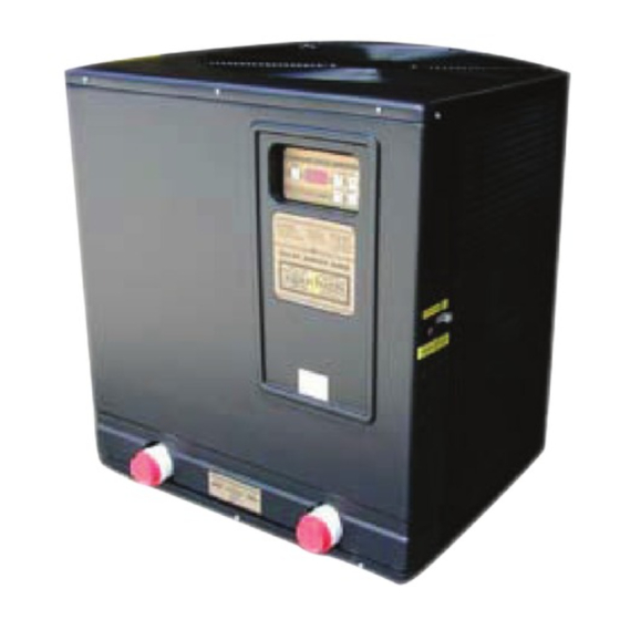
Model AT800 AT600 & AT400
"BLACK CABINET" with
NOTE: Installers should see separate installation manual !
WARNING: Specifications may change without notice.
HEAT PUMPS
OWNERS
DIGITAL CONTROL S S S S S ONLY
DIGITAL CONTROL
DIGITAL CONTROL
DIGITAL CONTROL
DIGITAL CONTROL
V2.3-AT © 2001 Calorex U.S.A. LLC
MEMBER
Pool
Heat
Pump
NATIONAL
Manufacturers
POOL & SPA
Association
INSTITUTE
ONLY
ONLY
ONLY
ONLY
Advertisement
Table of Contents

Subscribe to Our Youtube Channel
Related Manuals for Calorex DIGITAL LOGIC AT800


Summary of Contents for Calorex DIGITAL LOGIC AT800
- Page 1 “BLACK CABINET” with DIGITAL CONTROL DIGITAL CONTROL ONLY ONLY NOTE: Installers should see separate installation manual ! MEMBER Pool Heat Pump NATIONAL Manufacturers POOL & SPA Association INSTITUTE WARNING: Specifications may change without notice. V2.3-AT © 2001 Calorex U.S.A. LLC...
-
Page 2: Table Of Contents
Congratulations on the purchase of your new pool/spa heat pump. A Heat Pump is one of the most efficient ways to heat your pool or spa. Your heat pump was manufactured by Calorex USA, the very first company to produce swimming pool heat pumps. Since making the very first pool heat pump some 24 years ago, Calorex has become the industry leader in reliability and efficiency. -
Page 3: Unit Exterior Description
Unit Description AIR DISCHARGE FAN THERMOSTAT WARNING: ROTATING BLADE KEEP CONTROLS HANDS & HAIR CLEAR! WARNING POOL/SPA POOL/SPA SELECT SWITCH DANGER FROM ELECTRICAL SHOCK & ROTATING FAN ! OFF/ON SHUT OFF ALL POWER SWITCH BEFORE SERVICING ! CAUTION: MORE THAN ONE LED READOUT DISCONNECTION MAY BE SERIAL... - Page 4 “Digital Logic” Digital Control Panel Information HEATER ON/OFF: To start the heater press this button and it’s green light will come on. To disable the heater press this button and its green light will go off. THERMOSTAT BUTTONS: Pressing the + button will raise the set temperature. Pressing the - button will lower the set temperature.
- Page 5 GREEN POWER LIGHT: This light indicates that the heater has control power. WARNING: This is not a supply line power indicator and caution should be used since more than one power disconnection may be required to isolate the heater electrically. WARNING: If the optional Time Clock Override is installed, you must shut off the water pumps main power disconnect as well to eliminate all power to the heater.
-
Page 6: Operational Instructions
Operational Instructions When heating the pool or spa you should check the following items as they are all critical to the proper operation of the heater. 1. WATER FLOW Make sure all pool filters and traps are clean since the unit requires a minimum water flow in order to operate properly. -
Page 7: Time Delay Modes
5. TIME DELAY MODE This heater is equipped with an internal compressor time delay to allow the refrigerant to settle during start-up or restart cycles. When the heater is started the fan will run but the compressor will not start until the 3 to 5 minute delay has passed. The green heating light will be on when the compressor is running. - Page 8 Heat Pump Maintenance & Precautions Air Flow & Access Clearances AIR COIL (on 3 Sides) BASE (CONCRETE OR PREFAB) 1. Make sure the unit has a firm base. The heat pump will produce condensation (water) while in operation. You will notice water coming from the bottom drain ports when the unit is running.
- Page 9 Feeders, Chemicals & Water Balance This heat pump is equipped with the highest marine grade cupronickel alloy heat ex- changer that is designed to resist corrosion from normal pool water. The life and con- dition of the heat exchanger is directly related to the pool water chemical balance and chemical usage techniques.
-
Page 10: Owner Cleaning & Maintenance
Freezing Condition Precautions In areas where extended freezing conditions exist, the heater must be plumbed as shown here (and the installation manual), so it can be winterized. Water left inside the heater will freeze and cause damage. This plumbing setup will allow the use of pressur- ized air to clear the heat exchanger of water in preparation for an extended freeze. - Page 11 Warranty Service Before calling for warranty service you should check the following first: 1. Clean all filters and traps in the pool circulation system. Low water flow will cause the unit to shut down or cycle. 2. Check and adjust all water flow valves and adjust to the proper positions to insure proper water flow through the heater.
-
Page 12: Operational Sequence & Troubleshooting Flow Chart
Operational Sequence & Troubleshooting Flow Chart for “Digital Logic” Digital Control Models 220V Power Water Pump To Heater Timer Activates Green Power Light Water Pump Starts Flowing Water Pressure Water Press. SW LF Readout SW Closes Stays Open Displayed on LED No Water Flow Thermostat To Heater or... -
Page 13: L.l.c
U.S.A. L.L.C. 5826 Corporation Circle Ft. Myers Florida 33905 888-297-3826 www.calorexusa.com calorexusa@earthlink.net MEMBER Pool Heat Pump NATIONAL Manufacturers POOL & SPA Association INSTITUTE Specifications may change without notice. © 2000 Calorex U.S.A. LLC...
Need help?
Do you have a question about the DIGITAL LOGIC AT800 and is the answer not in the manual?
Questions and answers