Sign In
Upload
Manuals
Brands
Allied Telesis Manuals
Switch
AT-x210 Series
Allied Telesis AT-x210 Series Manuals
Manuals and User Guides for Allied Telesis AT-x210 Series. We have
1
Allied Telesis AT-x210 Series manual available for free PDF download: Installation Manual
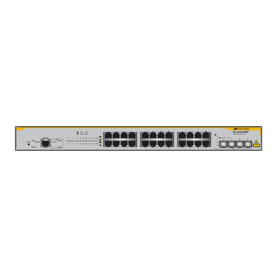
Allied Telesis AT-x210 Series Installation Manual (66 pages)
Gigabit
Brand:
Allied Telesis
| Category:
Switch
| Size: 3 MB
Table of Contents
Table of Contents
5
Preface
11
Symbol Conventions
12
Contacting Allied Telesis
13
Chapter 1: Overview
16
Features
16
Twisted Pair Ports
16
SFP Slots
16
Leds
17
Installation Options
17
Power Conservation
17
MAC Address Table
17
Package Contents
18
Figure 1: AT-X210-9GT, AT-X210-16GT, and AT-X210-24GT Packaging
18
Front and Back Panels
19
Figure 2: AT-X210-9GT, AT-X210-16GT, and AT-X210-24GT Front Panels
19
Figure 3: MODE LED Toggle Button
20
Figure 4: AT-X210-9GT, AT-X210-16GT, and AT-X210-24GT Back Panels
20
Management Software
21
Twisted Pair Ports
22
Leds
23
POWER/FAULT/STANDBY Leds
23
Figure 5: POWER LED on AT-X210-9GT
23
Table 1. AT-X210-9GT POWER LED Functional Descriptions
23
Figure 6: FAULT LED on AT-X210-9GT
24
Figure 7: FAULT LED on AT-X210-16GT
24
Table 2. AT-X210-16GT and AT-X210-24GT FAULT LED Functional Descriptions
24
Table 3. AT-X210-16GT and AT-X210-24GT STANDBY LED Functional Descriptions
24
10Base-T/100Base-TX/1000 Base-T Link Activity Leds
25
Figure 8: AT-X210-9GT Link/Activity and Speed Leds
25
Table 4. AT-X210-9GT LINK/ACT and SPEED/DUPLEX LED Descriptions
25
Figure 9: AT-X210-16GT Link/Activity/Speed Leds
26
Figure 10: AT-X210-24GT Link/Activity/Speed Port LED
26
SFP Leds
27
Figure 11: AT-X210-9GT SFP Speed and Link/Activity Leds
27
Table 5. AT-X210-16GT and AT-X210-24GT LINK/ACT and SPEED/DUPLEX LED Descriptions
27
Figure 12: AT-X210-16GT SFP Status Leds
28
Figure 13: AT-X210-24GT SFP Status Leds
28
Table 6. SFP Link/Activity LED Functional Descriptions
28
Power Supply
29
Chapter 2: Installation
32
Reviewing Safety Precautions
32
Selecting a Site for the Switch
34
Cable Specifications
35
Table 7. Twisted Pair Cabling and Distances
35
Unpacking the Switch
36
Installing the Switch on a Table or a Desktop
37
Figure 14: Attaching the Rubber Feet
37
Installing the Switch in an Equipment Rack
38
Figure 15: Turning the Switch Upside down
38
Figure 16: Attaching Brackets to an AT-X210-24GT
38
Figure 17: Mounting an AT-X210-24GT Switch in an Equipment Rack
39
Figure 18: Attaching the Brackets Level with the Front of an AT-X210-16GT
40
Figure 19: Close up Showing a Bracket Positioned for an AT-X210-9GT
40
Figure 20: Mounting an AT-X210-16GT Switch in an Equipment Rack
41
Figure 21: Fitting Rack Mount Handles to the Brackets for an AT-X210-9GT
42
Figure 22: Fitting Brackets to the Mounting for an AT-X210-9GT
42
Figure 23: Attaching Cable Tray Brackets for an AT-X210-9GT
43
Figure 24: Mounting an AT-X210-9GT Switch in an Equipment Rack
43
Figure 25: Mounting an AT-X210-9GT Switch in an Equipment Rack
44
Figure 26: Securing Cables to the Cable Tray for an AT-X210-9GT
44
Installing Optional SFP Transceivers
45
Figure 27: Removing the Dust Plug from an SFP Slot
45
Figure 28: Inserting the SFP on an AT-X210-24GT
46
Figure 29: Inserting the SFP on an AT-X210-16GT
46
Figure 30: Positioning the SFP Handle in the Upright Position
47
Figure 31: Ejecting an SFP Transceiver after Lowering the SFP Handle to the Downwards Position
47
Cabling the Switch
49
Powering on the Switch
51
Figure 32: Lifting the AC Power Cable Hook on an AT-X210-16GT Switch
51
Figure 33: Plugging in the AC Power Cord on an AT-X210-16GT Switch
51
Monitoring the Initialization Processes
53
Figure 34: Switch Initialization Messages
53
Figure 35: Switch Initialization Messages (Continued)
54
Figure 36: Switch Initialization Messages (Continued)
55
Chapter 3: Troubleshooting
57
Appendix A: Physical Specifications
62
Dimensions
62
Weight
62
Environmental Specifications
62
Table 8. Chassis Dimensions
62
Table 9. Chassis Weight
62
Table 10. Environmental Specifications
62
Power Specifications
63
Electrical Safety and Electromagnetic Emissions Certifications
63
Table 11. Power Specifications
63
Table 12. Safety and Electromagnetic Emissions Certifications
63
Connectors and Port Pinouts
64
Figure 37: RJ-45 Connector and Port Pin Layout
64
Table 13. MDI Pin Signals (10Base-T or 100Base-TX)
64
Table 14. MDI-X Pin Signals (10Base-T or 100Base-TX)
64
Table 15. RJ-45 1000Base-T Connector Pinouts
65
Advertisement
Advertisement
Related Products
Allied Telesis AT-x210-9GT
Allied Telesis AT-x210-16GT
Allied Telesis AT-x210-24GT
Allied Telesis AT-x230-10GP
Allied Telesis AT-x230-18GP
Allied Telesis AT-x230-28GP
Allied Telesis AT-x230-18GT
Allied Telesis AT-x230-28GT
Allied Telesis AT-x220-28GS
Allied Telesis AT-x230L-17GT
Allied Telesis Categories
Switch
Network Router
Media Converter
Network Hardware
Wireless Access Point
More Allied Telesis Manuals
Login
Sign In
OR
Sign in with Facebook
Sign in with Google
Upload manual
Upload from disk
Upload from URL