Husqvarna DC 6000 Workshop Manual
Hide thumbs
Also See for DC 6000:
- Operator's manual (84 pages) ,
- Operator's manual (60 pages) ,
- Operator's manual (104 pages)
Table of Contents
Advertisement
Advertisement
Table of Contents

Related Manuals for Husqvarna DC 6000


Summary of Contents for Husqvarna DC 6000
- Page 1 Workshop manual DC 6000 115 63 33-26 HUSQVARNA CONSTRUCTION PRODUCTS...
- Page 2 LEGEND...
-
Page 3: Table Of Contents
Machine Stop Button ����������������������������������������������������������������������������������������������������������������������������������� 7 5. Specification Technical Data ����������������������������������������������������������������������������������������������������������������������������������������������� 8 6. Tools and Special Tools Tools ��������������������������������������������������������������������������������������������������������������������������������������������������������������� 9 7. Components - Navigation DC 6000 ������������������������������������������������������������������������������������������������������������������������������������������������������10 Electrical box �����������������������������������������������������������������������������������������������������������������������������������������������11 Electrical box Lower �����������������������������������������������������������������������������������������������������������������������������������12 8. Function Test Function Test �����������������������������������������������������������������������������������������������������������������������������������������������13 Electrical Functions ������������������������������������������������������������������������������������������������������������������������������������14 Simplified Electrical Schematic ����������������������������������������������������������������������������������������������������������������15... - Page 4 TABLE OF CONTENTS 11. Repair Instructions 11.1. Covers Removing the Front Cover ������������������������������������������������������������������������������������������������������������������������32 11.2. Electric Replacing the Main Cable �������������������������������������������������������������������������������������������������������������������������33 Removing Terminal Block X1 �������������������������������������������������������������������������������������������������������������������33 Removing Terminal Block X2 �������������������������������������������������������������������������������������������������������������������34 Removing Contact Blocks H1, H2, S1, S2, S3, S4, S7 ��������������������������������������������������������������������������34 Removing Fuse F3 ��������������������������������������������������������������������������������������������������������������������������������������34 Removing Fuse F3 ��������������������������������������������������������������������������������������������������������������������������������������35 Removing Relay K4 ������������������������������������������������������������������������������������������������������������������������������������35...
-
Page 5: Literature
3. LITERATURE Workshop Manual The workshop manual covers all workshop maintenance for the DC 6000. Some very simple and ob- vious repair work has been omitted. The manual is divided into numbered chapters as well as chapter headings that are specified in bold at the top of each page �... -
Page 6: Safety Instructions
General • No one may repair the DC 6000 unless they have read and understood the contents of this workshop manual. • This workshop manual is written for personnel with general knowledge about the repair and service of DC 6000. -
Page 7: Machine Stop Button
Machine Stop Button The DC 6000 is equipped with an machine stop button which will quickly shut down power to the DC 6000. Note that the electrical cabinet will still be energized even when the machine stop button is pushed. -
Page 8: Specification
SPECIFICATION 5. SPECIFICATION Technical Data DC 6000 Data Power, kW 7,75 Rated voltage, V 480/400 Rated current, A 15,9 Power supply 3 phase Airflow, cfm/l/s Max� vacuum, bar/psi 0,42/3,05 Suction inlet diameter mm/inch 75/3 Total filter area, m2 7�8/84 Weight, kg/lbs... -
Page 9: Tools And Special Tools
TOOLS AND SPECIAL TOOLS 6. TOOLS AND SPECIAL TOOLS In the list below you will find the tools and the special tools used in this workshop manual. Tools Tool Tool no. Description Ratchet Wrench Wrench Socket Allen Key, Kit 2�5 - 10 mm Universal Pliers Pliers Screwdriver... -
Page 10: Components - Navigation
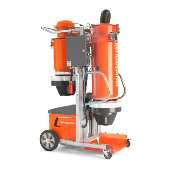
COMPONENTS - NAVIGATION 7. COMPONENTS - NAVIGATION DC 6000 1� Pressure Chamber 6� Lower electrical enclosure 2� Cyclone container 7� Blower Motor 3� Electrical Cabinet 8� Frame 4� Power Cable 5� Filter Holder... -
Page 11: Electrical Box
COMPONENTS - NAVIGATION Electrical box 1� Contactor, K1 12� Overload protection, Q2 2� Contactor, K2 13� Hour meter, CR1 3� Fuse holder, F1, Fuse F1 14� PLC, CR2 4� Phase sequence relay, K3 15� Pushbutton white, S7 5� Relay, K4 16�... -
Page 12: Electrical Box Lower
COMPONENTS - NAVIGATION Electrical box Lower 1� Transformer, T1 3� Pressure switch, S10 2� Compressor capacitor, C1 4� Valve connector, X3... -
Page 13: Function Test
FUNCTION TEST 8. FUNCTION TEST Function Test • Connect the Vacuum to a power outlet� • Push the green button. A white lamp is lit up, and the compressor will start to build up pressure. It can take around 30 seconds until the compressor has reached the correct pressure. (Note: if the correct pressure is main tained the compressor won’t engage) •... -
Page 14: Electrical Functions
FUNCTION TEST Electrical Functions The electrical functions of the DC6000 are divided in a 400/480 V 3-Phase system and a 1-phase 230 V system. The 400/480 V 3-Phase system is used to power the Blower Motor and to power the Auxiliary power outlet used to power the connected grinder. -
Page 15: Simplified Electrical Schematic
FUNCTION TEST Simplified Electrical Schematic... -
Page 16: Blower Motor
FUNCTION TEST Blower Motor The blower motor is powered by the 400/480 V 3-phase system and is controlled by the PLC. The PLC sends a 230 V signal to the overload protection Q1 and it engages one of the 2 power contactors K1 and K2. The phase sequence re- lay K3 determines which one the contactors that engages according to how the phases in are connected. -
Page 17: Blower Motor Electrical Schematic
FUNCTION TEST Blower Motor Electrical Schematic... -
Page 18: Auxiliary Power Outlet
FUNCTION TEST Auxiliary Power Outlet The auxiliary outlet is connected directly to the main power cable and is energized as soon as the main cable is con- nected to a power source. -
Page 19: Auxiliary Power Outlet Electrical Schematic
FUNCTION TEST Auxiliary Power Outlet Electrical Schematic... -
Page 20: Plc
FUNCTION TEST The PLC is powered by the 230 V transformer and is used to control the on/off function for the blower. And the manual/automatic purge function. Its input is controlled by the settings on the control panel. And its output is a 230 V control signal for the purge solenoid and to the blower. -
Page 21: Plc Electrical Schematic
FUNCTION TEST PLC Electrical Schematic... -
Page 22: Transformer 230V
FUNCTION TEST Transformer 230V The 230V Transformer transforms 400/480V 3-phase power to 230V 1-phase power. The 230V is used to power the PLC, the Air Compressor and its pressure switch. All of the in/out signals from the PLC are also a part of the 230V electrical system��... -
Page 23: Transformer 230V Electrical Schematic
FUNCTION TEST Transformer 230V Electrical Schematic... -
Page 24: Purge Function
FUNCTION TEST Purge Function The Purge function is the automatic filter cleaning system. It cleans the airfilter by releasing compressed air through the filter which allows the dust to fall down in the longopac bag. The Purge function can be in Automatic or Manual mode. -
Page 25: Purge Function Electrical Schematic
FUNCTION TEST Purge Function Electrical Schematic... -
Page 26: Hour Meter
FUNCTION TEST Hour Meter The Hour meter is used show the running time for the blower motor. Its mounted in the electrical cabinet and reads the signal between the Overload Protection (Q1) and the Phase sequence relay (K3). -
Page 27: Hour Meter Electrical Schematic
FUNCTION TEST Hour Meter Electrical Schematic... -
Page 28: Troubleshooting
TROUBLESHOOTING TROUBLESHOOTING Troubleshooting WARNING! Most accidents involving machines occur during trouble shooting, service and maintenance as staff have to locate themselves within the machine’s risk area. Prevent accidents by being alert and by planning and preparing the work� The engine should be switched off during operations described in this chapter unless otherwise stated. All checks involving electric components should only be performed by a licensed electrician. -
Page 29: 10. Service And Maintenance
Clean the machine exterior� Check the filter and shake out the dust when needed. If necessary, wash the filter with water according to Husqvarna's recommendations. Never clean the filter using air pressure. See Cleaning / replace filters in OM Check the dust level inside the filter housing. -
Page 30: Filter Maintenance
SERVICE AND MAINTENANCE Filter The filter is made of a polyester material and can be washed with water as necessary. Change filter after 500 hours or after 6 months� •In order to avoid destruction of the finish or ePTFE membrane clean the filter elements with a gentle soft jet of water. -
Page 31: 11. Repair Instructions
REPAIR INSTRUCTIONS REPAIR INSTRUCTIONS 11. REPAIR INSTRUCTIONS 11.1. Covers Removing the Front Cover ���������������������������������������������������������������������������������������������������������������������32 11.2. Electric Replacing the Main Cable ����������������������������������������������������������������������������������������������������������������������33 Removing Terminal Block X1 ����������������������������������������������������������������������������������������������������������������33 Removing Terminal Block X2 ����������������������������������������������������������������������������������������������������������������34 Removing Contact Blocks H1, H2, S1, S2, S3, S4, S7 �����������������������������������������������������������������������34 Removing Fuse F3 �����������������������������������������������������������������������������������������������������������������������������������34 Removing Fuse F3 �����������������������������������������������������������������������������������������������������������������������������������35 Removing Relay K4 ���������������������������������������������������������������������������������������������������������������������������������35... -
Page 32: 11.1. Covers
11.1 COVERS 11.1. COVERS Removing the Front Cover 1� Remove the four screws holding the top cover� 2� Lift the top cover up and outwards. 3� Remove the seven screws holding the front cover� Remove the front cover by pulling it out�... -
Page 33: 11.2. Electric
ELECTRIC 11.2 11.2. ELECTRIC Replacing the Main Cable 1� Open the electrical box� 2� Remove the cables� 3� Unscrew the cap and pull out the main cable� Reverse steps for assembly� Removing Terminal Block X1 1� Remove the Clamp using a screwdriver. -
Page 34: Removing Terminal Block X2
11.2 ELECTRIC Removing Terminal Block X2 1� Remove the Clamp using a screwdriver. 2� Remove the 5-way Jumper Bar by pulling it out� 3� Pry the Terminal Block of by using a flat crewdriver. Removing Contact Blocks H1, H2, S1, S2, S3, S4, S7 1�... -
Page 35: Removing Fuse F3
ELECTRIC 11.2 Removing Fuse F3 1� Remove the Fuse by opening the fuse holder and pull the fuse out. 2� Remove the Fuse holder by pushing it down and turning it out� Removing Relay K4 1� Remove the Relay by flipping the plastic holder and pull the relay out�... -
Page 36: Removing Plc Cr2
11.2 ELECTRIC Removing PLC CR2 1� Remove the PLC Eaton by pushing it down and turning it out� Removing Contactors K1, K2, Q1 1� Remove the Contactor by pushing it down and turning it out. -
Page 37: Replace Transformer
ELECTRIC 11.2 Replace Transformer First see Removing the Front Cover (p. 32) 1� Remove lid and seal with four screws� 2� Remove ground cable with nut and washer. 3� Remove the three locking nuts and washers. 4� Remove the two cables from the Terminal Blocks using a flat crewdriver. -
Page 38: 11.3. Motor
11.3 MOTOR MOTOR 11.3. MOTOR Remove Air Hose First see Removing the Front Cover (p. 32) 1� Remove the connection from the top cap� 2� Open the electrical box by removing the four screws from the lid. 3� Disconnect the hose from the switch and remove the connection�... -
Page 39: Removing Generator
MOTOR MOTOR 11.3 Removing Generator First see Removing the Front Cover (p. 32) 1� Remove lid and seal with four screws� 2� Remove all 4 wires to the Compressor Capacitor and the Valve connector, X3 3� Unscrew the cable connector and pull the wires out�... -
Page 40: Removing Motor
11.3 MOTOR Removing Motor First see Removing the Front Cover (p. 32) High Voltage 1� Slip a 2”4 under the motor. 2� Unscrew the four screws holding the front end of the frame. 3� Remove the loose frame� 4� Open up the electrical box on the motor�... -
Page 41: Filter
FILTER 11.4 Replace Filter Valve 1� Remove the hose connection from the cap� 2� Unscrew the cable grommet� 3� Remove the 6 screws and washers from the plate� 4� Remove the screw and washer holding the ground cable. 5� Lift the top up� 6�... -
Page 42: Replace Filter Sealing
11.4 FILTER Replace Filter Sealing 1� Remove the hose connection from the cap� 2� Unscrew the cable grommet� 3� Remove the 6 screws and washers from the plate� 4� Remove the screw and washer holding the ground cable. 5� Lift the top up� 6�... -
Page 43: Electrical Drawings
ELECTRICAL DRAWINGS 11.5 Controls CE... -
Page 44: Controls
11.5 ELECTRICAL DRAWINGS Controls US... -
Page 45: Power
ELECTRICAL DRAWINGS 11.5 Power CE... -
Page 46: Power
11.5 ELECTRICAL DRAWINGS Power US... - Page 47 COVERS 10.3 www.husqvarnacp.com 115 63 33-26 English...
Need help?
Do you have a question about the DC 6000 and is the answer not in the manual?
Questions and answers