Table of Contents
Advertisement
Quick Links
Instruction Manual book
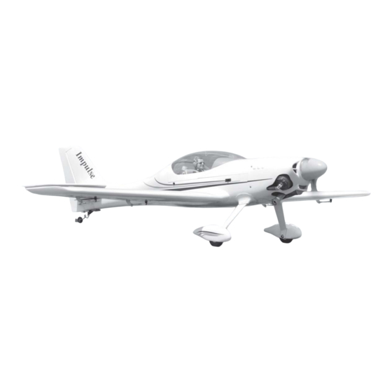
SPECIFICATION
Wingspan :
Length
Weight
Radio
Servo
Engine
Electric Motor: RIMFIRE.80
Battery: 5-6 Cells-Li-Poly 18.5 -22.2V-5.500mAh.
Propeller: 15X 6
Speed control: 60A.
1,750 mm
:
1,285 mm
:
4,4 kg
:
07 channels.
:
08 servos.
:
55 - 2 Stroke
15 -20CC Gas.
68.90 in.
50.59 in.
9.68 Lbs.
Made in Vietnam.
ITEM CODE:BH 121.
Advertisement
Table of Contents

Related Manuals for Black Horse Model Impulse 100TD


Summary of Contents for Black Horse Model Impulse 100TD
- Page 1 Instruction Manual book ITEM CODE:BH 121. SPECIFICATION Wingspan : 1,750 mm 68.90 in. Length 1,285 mm 50.59 in. Weight 4,4 kg 9.68 Lbs. Radio 07 channels.
- Page 2 - Item code: BH 121 This instruction manual is designed to help you build a great flying aeroplane. Please read this manual thoroughly before starting assembly of your Impulse 100TD. Use the parts listing below to identify all parts. WARNING.
-
Page 3: Safety Precaution
Impulse 100TD Instruction Manual - Item code: BH 121 Wing warp: Hold the panel twisted Caution: this model is not a toy! gently in the opposite If you are a beginner to this type of powered direction to the warp, and... -
Page 4: Installing The Aileron Servo
Impulse 100TD Instruction Manual - Item code: BH 121 REPLACEMENT SMALL PARTS 1. Aluminium landing gear.(Right & Left). Bottom side 2. Wheel pants. 3. Fuel Tank. 4. Engine mount ply of wood . 5. Tail gear set. 6. Plastic parts for landing gear. - Page 5 Impulse 100TD Instruction Manual - Item code: BH 121 Assemble then apply drops of thin C/A to center of hinge,on both sides. 3. Drill 1,5mm pilot holes through the block of wood for each of the four mounting screws provided with the servo. Install servo into ai- leron servo tray as same as picture below.
-
Page 6: Installing The Aileron Linkages
Impulse 100TD Instruction Manual - Item code: BH 121 A+B Epoxy PLUS 5. Instal servo tray with aileron servo into the wing as same as picture below. 2x10mm. Secure. Control horn of the aileron Repeat the procedure for the other wing half. - Page 7 Impulse 100TD Instruction Manual - Item code: BH 121 2x10mm. Secure. II. FLAP 1. INSTALLING THE FLAP SERVO . Thread 2. INSTALLING THE FLAP CONTROL HORN. Control horn of the flap Electric wire A+B Epoxy PLUS...
- Page 8 Impulse 100TD Instruction Manual - Item code: BH 121 Control horn of the flap 3.INSTALLING THE FLAP LINKAGES. Bottom side Installing the aileron linkages as pictures below. Aileron Flap 60 mm Repeat the procedure for the other wing half. THERE ARE TWO OPTIONS: 1.
- Page 9 Impulse 100TD Instruction Manual - Item code: BH 121 Drill a hole 2mm diameter. R e m o v e Wood. 3x 15mm Secure. C/A glue.
-
Page 10: Installing The Engine Mount
Impulse 100TD Instruction Manual - Item code: BH 121 Motor. 3 x 15mm Rotor sharft. Front view. Left side. Secure. Right side Front view. OPTION 2: ENGINE MOUNT INSTALLING THE ENGINE MOUNT. See pictures below: 5x 80mm Battery. - Page 11 Impulse 100TD Instruction Manual - Item code: BH 121 INSTALLING THE THROTTLE - CABLE. 1. Install one adjustable metal connector through the third hole out from the center of one servo arm, enlarge the hole in the servo arm using a 2mm drill bit to accommodate the servo connector.
-
Page 12: Installing The Stopper Assembly
Impulse 100TD Instruction Manual - Item code: BH 121 3) Carefully bend the second nylon tube up at a 45 degree angle (using a cigarette lighter). This tube will be the vent tube to the muffler. 4) Carefully bend the third nylon tube down at a 45 degree angle (using a cigarette lighter). - Page 13 Impulse 100TD Instruction Manual - Item code: BH 121 5) Test fit the stopper assembly into the 9) To secure the fuel tank in place, apply a tank. It may be necessary to remove some of bead of silicon sealer to the forward area of...
- Page 14 Impulse 100TD Instruction Manual - Item code: BH 121 COWLING. center line 1. 1. Slide the fiberglass cowl over the en- gine and line up the back edge of the cowl with the marks you made on the fuselage.
- Page 15 Impulse 100TD Instruction Manual - Item code: BH 121 center line 2 Drill 2mm hole. Trim and cut. Trim and cut. 2. While keeping the back edge of the cowl flush with the marks, align the front of the cowl with the crankshaft of the engine. The...
-
Page 16: Installing The Spinner
Impulse 100TD Instruction Manual - Item code: BH 121 Secure. Front view INSTALLING THE SPINNER. Install the spinner backplate, propeller and spinner cone. The spinner cone is held in place using two 3mm x 8mm machine screws. Secure. -
Page 17: Installing The Elevator Servos
Impulse 100TD Instruction Manual - Item code: BH 121 INSTALLING THE ELEVATOR SERVOS. Cut the covering 1. Install the rubber grommets and brass away from the slot. collets into the elevator servo. Test fit the servo into the servo tray. -
Page 18: Elevator Control Horn Installa- Tion
Impulse 100TD Instruction Manual - Item code: BH 121 165 mm C/A glue. Bottom side. ELEVATOR CONTROL HORN INSTALLA- TION. Elevator control horn install as same as the way of aileron control horn. Please see pictures below. Control horn of Elevator. -
Page 19: Elevator Pushrod Installation
Impulse 100TD Instruction Manual - Item code: BH 121 E l e v a t o r E l e v a t o r pushrod pushrod Bottom side M2 lock nut. Elevator control horn. ELEVATOR PUSHROD INSTALLATION. Elevator pushrod install as same as the way of aileron pushrod. -
Page 20: Rudder Control Horn Installa- Tion
Impulse 100TD Instruction Manual - Item code: BH 121 When you are sure that everything is a aligned correctly, mix up a generous amount of 30 minute epoxy. Apply a thin layer to the slot in the mounting platform and to the verti- cal stabilizer mounting area. -
Page 21: Rudder Pushrod Installation
Impulse 100TD Instruction Manual - Item code: BH 121 Rudder control horn. Cut. RUDDER PUSHROD INSTALLATION. Rudder pushrod install as same as the way of aileron pushrod. M2 lock nut. C/A glue. Rudder pushrod. C/A glue. Bottom side Plastic parts of elevator and rudder pushrod. -
Page 22: Mounting The Tail Wheel Bracket
Impulse 100TD Instruction Manual - Item code: BH 121 MOUNTING THE TAIL WHEEL BRACKET. 1. Set the tail wheel assembly in place on the plywood plate. The pivot point of the tail wheel wire should be even with the rud- der hinge line and the tail wheel bracket should be centered on the plywood plate. -
Page 23: Installing The Main Landing Gear
Impulse 100TD Instruction Manual - Item code: BH 121 2) A drop of C/A glue on the wheel collar screws will help keep them from coming lose during operation. Repeat the process for the other wheel. INSTALLING THE MAIN LANDING GEAR 1) The blind nuts are already mounted in- side the fuselage. -
Page 24: Installing The Switch
Impulse 100TD Instruction Manual - Item code: BH 121 C/A glue Repeat the procedure for the other wing half. Bottom side. 4x15mm INSTALLING THE SWITCH. 1. Cut out the switch hole using a modeling knife. -
Page 25: Wing Attachment
Impulse 100TD Instruction Manual - Item code: BH 121 Switch of receiver. Receiver. INSTALLING THE RECEIVER AND BATTERY. 1. Plug the servo leads and the switch lead into the receiver. You may want to plug... - Page 26 Impulse 100TD Instruction Manual - Item code: BH 121 2. Attach the aluminium tube into the 3. Insert two wing panels as pictures fuselage. below. Left wing Left wing. Secure. Fuselage top hatch. See picture wing attach to fuselage.
-
Page 27: Control Throws
Impulse 100TD Instruction Manual - Item code: BH 121 *If possible, first attempt to balance the model Top side. by changing the position of the receiver bat- tery and receiver. If you are unable to obtain good balance by doing so, then it will be nec- essary to add weight to the nose or tail to achieve the proper balance point. -
Page 28: Pre-Flight Check
Impulse 100TD Instruction Manual - Item code: BH 121 15mm 15mm Aileron control 20mm Flap control 10mm 10mm Elevator control 12mm 12mm Rudder control PRE-FLIGHT CHECK. 1) Completely charge your transmitter and receiver batteries before your first day of fly- ing.
Need help?
Do you have a question about the Impulse 100TD and is the answer not in the manual?
Questions and answers