Advertisement
Quick Links
8-line Digital I/O to Ethernet Adapter, w/ DIN
1. Introduction
Thank you for purchasing this 8-line Digital I/O to Ethernet Adapter
(hereinafter referred to as "Adapter"). It is designed to adopt your
digital I/O lines remotely on your Ethernet (Internet). It delivers simple,
reliable and cost-effective network connectivity for your digital I/O
applications such as home or industrial factory automation, digital I/O
control from any networked PC, alarm and power monitoring by
network or Internet, PC controlled machines, distributed machine
I/O, remote lighting and power control etc.
Features:
4 Digital Input and 4 Output Lines over a 10-pin Terminal Blocks
2 Non-inverted and 2 Inverted Output Lines
Provides ESD and Surge Protection for all I/O Lines
I/O Line Voltage is Compatible with CMOS/TTL
Provides one 10/100Mbps, RJ45 LAN Port
Provides TCP Server, TCP Client, and I/O Extender Modes
Powered +5VDC by DC Jack or Terminal Blocks
Provides both Wall Mounting and DIN RAIL Kits
Supports Virtual COM Port Drivers
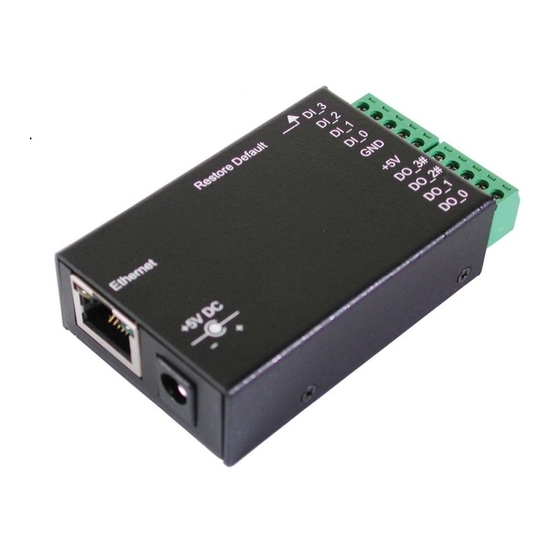
2. Connector Layout
Switch to Restore
Default Settings
RJ45 LAN
Connector
+5VDC Power
Input DC Jack
EX-6011
RAIL Mounting Kit
1
DIO Lines Terminal
Blocks
Advertisement

Related Manuals for Exsys EX-6011


Summary of Contents for Exsys EX-6011
- Page 1 EX-6011 8-line Digital I/O to Ethernet Adapter, w/ DIN RAIL Mounting Kit 1. Introduction Thank you for purchasing this 8-line Digital I/O to Ethernet Adapter (hereinafter referred to as “Adapter”). It is designed to adopt your digital I/O lines remotely on your Ethernet (Internet). It delivers simple,...
- Page 2 8-line Digital I/O to Ethernet Adapter Link/Activity LED 10/100 Mbps LED (green color) (amber color) Power Input DC Jack Connector 10-pin Terminal Blocks: This pluggable terminal blocks integrates 4 digital input and 4 digital output I/O lines (CMOS/TTL Level). Its pin assignment as the following table.
-
Page 3: Hardware Installation
8-line Digital I/O to Ethernet Adapter DC Jack Power Connector: A 5V/2A AC adapter is supplied with this product. RJ45 Ethernet Connector: 10/100Mbps Ethernet port. It supports auto cross-over feature. You can use the same cable to connect to either a Hub/Switch or a host computer. LED Indicators: There are 2 LAN LEDs on the rear panel. -
Page 4: Configuring The Adapter
8-line Digital I/O to Ethernet Adapter Wall Mount DIN RAIL Mount DIN RAIL Mount (Vertical) (Horizontal) 4. Configuring the Adapter Setting IP Address Please consult your Network Administrator to determine the appropriate IP address for the Adapter. The IP address can be set in any of the following ways: Automatically from a DHCP Server Web Browser... - Page 5 8-line Digital I/O to Ethernet Adapter Setting the IP address using Web Browser Please make sure your PC’s IP address is set at the same subnet of the Adapter. If not, you usually need to change your PC’s IP address from “Local Area Connection Properties”, here is an example to show you how to change your PC’s IP address:...
- Page 6 8-line Digital I/O to Ethernet Adapter Run your browser and access the Adapter by entering the default (192.168.1.254) or current IP address into your browser’s address window. Enter the password (default has no password). Then go to change your IP address as well other parameters if required.
- Page 7 8-line Digital I/O to Ethernet Adapter E:\IO_over_IP\Utilities\Em\Em.exe Double-click here will go to the Setup Menu Note: If the Setup Menu does not appear after double- clicked the listed item on the above screen, you may need to disable your firewall or the anti-virus software then try again. The Adapter Settings When you entered Setup Menu of the Adapter, the following page will be available for your access.
- Page 8 8-line Digital I/O to Ethernet Adapter Item Description 4 numbers separated by dots, it can be assigned IP address by the DHCP server if “DHCP client” is enabled. 4 numbers separated by dots, can be assigned by Subnet mask the DCHP server if “DHCP client” is enabled. 4 numbers separated by dots, can be assigned by Gateway address the DCHP server if “DHCP client”...
- Page 9 8-line Digital I/O to Ethernet Adapter Server without connection. IO Extender Master, uses Master Server protocol, passively waits for IO Extender Slave IO Extender Slave, uses Slave Client protocol, actively connects to IO Extender Master Only valid for TCP client, UDP, IO Extender Slave modes: Destination IP address/ Enter the Server IP address and port number when...
- Page 10 8-line Digital I/O to Ethernet Adapter Launch the HyperTerm utility, it will create a new connection, please type the connection name (type “a” in this case). Enter the Adapter’s IP address and port number:...
- Page 11 8-line Digital I/O to Ethernet Adapter Once the connection is built up successfully, the HyperTerm will receive 10-byte (ASCII) string characters plus carriage-return and a line-feed) indicating the current state of all 8 DIO lines, “11111111” for example. The string is formatted as the following table: 1 1 1 1 1 1 1 1 DI_3 DI_2...
- Page 12 8-line Digital I/O to Ethernet Adapter At this point you may key in command strings to change the digital output line state or read their current state. For example: where nn = Output pin number, there are four legal values: 01, 02, 03 and 04 m = 0 or 1, 0 means to drive the I/O pin to LOW state, 1 means to set the I/O pin to HIGH state.
- Page 13 8-line Digital I/O to Ethernet Adapter Status: Current state sent from Adapter Command: Set Output #1 to 0 Command: Set Output#2 to 0 Command: Set Output#1 to 1 Command: Set Output#2 to 1 Press Enter only: Null command, to read current state Error command: No response The 4 digital input pins are always monitored and de-bounced by the firmware.
- Page 14 8-line Digital I/O to Ethernet Adapter DI_0 is grounded to 0 Released DI_1 is grounded to 0 Released DI_2 is grounded to 0 Released DI_3 is grounded to 0 Released 6. Using Virtual COM Port Drivers This digital I/O Adapter can work in ether Straight IP mode or Virtual COM Port mode.
- Page 15 8-line Digital I/O to Ethernet Adapter While installing the driver, please enter the password: Follow the on-screen instructions to complete the Installation, you are ready to launch the software utility to enter the hardware settings to function properly.
- Page 16 8-line Digital I/O to Ethernet Adapter Launch CentosSEC After installed the CentosSEC, you will need to navigate either to the Start Menu and locate the launcher in Programs submenu or double-click the shortcut created on the desktop. Please note that CentosSEC should be run as an administrator, for some Windows such as 2008, Vista and 7, their UAC (User Account Control) will limit the CentosSEC from working properly if you have only standard user...
- Page 17 8-line Digital I/O to Ethernet Adapter Configuring CentosSEC Running the CentoSEC, the following screen will appear, click the Help button will list the supported operations and details. You may need to click Add to create a new COM port then click Update All to save the settings.
- Page 18 8-line Digital I/O to Ethernet Adapter It is important to set the Net. Protocol to RAW instead of TELNET for this digital I/O Adapter. After clicked Update All button, the status field should become “Available”. If it is “Registered”, it won’t work properly.
-
Page 19: Operation Modes
8-line Digital I/O to Ethernet Adapter 7. Operation Modes The Adapter can function as a server or client for TCP and UDP connections. The application scenarios include TCP Server mode, TCP Client mode, UDP mode, IO Extender Master/Slave (Paired) mode. When in IO Extender Master/Salve Paired mode, one Adapter must be set as IO Extender Master and the other as IO Extender Slave mode, the paired mode extends the digital IO lines remotely without... - Page 20 8-line Digital I/O to Ethernet Adapter IO Extender Master/Salve (Paired) mode: The IO Extender mode is designed for 2 digital IO Adapters to be connected in back-to-back via Ethernet (Internet). The 4 digital inputs of one unit will be driven by the 4 digital outputs of the other unit. Please refer to the following diagram.
- Page 21 8-line Digital I/O to Ethernet Adapter IO Extender Slave Configuration: The Slave unit settings included its IP address (192.168.1.252, must be different from the Master unit), mode (IO Extender Slave) and Destination IP/port (Master unit’s IP/port, 192.168.1.254 port 100) to request for the service connection.
-
Page 22: Product Specifications
8-line Digital I/O to Ethernet Adapter 6. Product Specifications Type Specifications 10/100Mbps Ethernet Connector RJ45 Speed 10/100Mbps Digital I/Os No. of Digital Inputs 4 TTL/CMOS Input Lines (DI_0 to DI_3) No. of Digital Outputs 4 TTL/CMOS Output Lines: (DO_0, DO_1, DO_2#, DO_3#) Connector 10-pin Terminal Blocks Surge Protection... - Page 23 8-line Digital I/O to Ethernet Adapter Operating Humidity 5 to 95% RH Electrical Characteristics Parameters Values Input: DI_0, DI_1, DI_2, DI_3 < 0.8V High > 2.0V Output: DO_0, DO_1, DO_2#, DO_3# < 0.55V High > 2.4V...
- Page 24 8-line Digital I/O to Ethernet Adapter...
Need help?
Do you have a question about the EX-6011 and is the answer not in the manual?
Questions and answers