Zimmer OptonPro Instructions For Use Manual
Hide thumbs
Also See for OptonPro:
- Instructions for use manual (60 pages) ,
- Operating instructions manual (54 pages) ,
- Instructions for use manual (48 pages)
Table of Contents
Advertisement
Quick Links
Advertisement
Table of Contents

Subscribe to Our Youtube Channel
Related Manuals for Zimmer OptonPro


Summary of Contents for Zimmer OptonPro
- Page 1 Instructions for Use OptonPro...
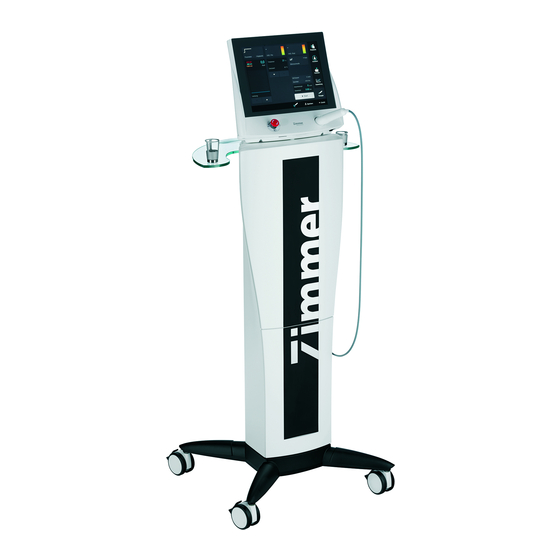
- Page 2 Figures Front view of device Fig. 1 Selection and control elements Control unit Display Emergency Off button SD card slot On/off switch Applicator with fibre-optic cable and power control sensor Applicator Fibre-optic cable Power control sensor and holder for applicator...
- Page 3 Figures Display Fig. 2 Screen readouts Status bar Buttons on the screen Title bar Navigation bar...
- Page 4 Figures Rear Fig. 3 18 / 19 Connector sockets Footswitch socket Interlock socket Connector for mains cable Holder for mains fuse Name plate 18 / 19 Socket without function for OptonPro Fibre-optic cable outlet...
- Page 5 Figures Accessories Fig. 4 22 Spacer small 23 Spacer large 24 Footswitch (optional) (optional) 25 Interlock key 26 Interlock switch 27 Laser protective glasses (optional) 28 Laser warning sign and lamp...
- Page 6 Explanation of symbols Caution laser aperture Turn the Emergency Off button in the direction of the arrows to unlock Device type BF Footswitch socket Interlock socket Value of the accessible fuses The device is protection class II. Follow operating instructions Serial number Article number...
- Page 7 Explanation of symbols Manufacturer Date of manufacturing In the user manual, this symbol stands for Caution. Please refer to Precautionary Definitions. In the user manual, this symbol stands for Warning. Please refer to Precautionary Definitions. In the user manual, this symbol stands for Danger. Please refer to Precautionary Definitions.
-
Page 8: Table Of Contents
1.4.2 Warning 1.4.3 Danger 1.4.4 Application Information 1.4.5 Protective measures and equipment at the workplace Common terms OptonPro – briefly Installation Safety measures Installation, starting the system Settings Navigation bar Instructions for use General operation Thermal threshold test Saving programmes... - Page 9 CE mark, legal information Errors, troubleshooting, disposal Manufacturer's EMC declaration Valid for the OptonPro. These operating instructions are an integral part of the device. They must be stored with the device and kept accessible at all times for anyone authorised to operate this device.
-
Page 10: Indications, Contraindications, Safety Instructions
Indications, Contraindications, Safety Instructions 1.1. Precautionary Definitions The precautionary instructions throughout the manual are indicated by specific symbols. Understand these symbols and their definitions before operating this equipment. The definition of these symbols are as follows: Text with “Caution” indicator will explain possible safety infractions that could have the potential to cause minor to moderate injury or damage to equipment. -
Page 11: Indications
Safety Instructions 1.2. Indications / 1.3. Contraindications Indications The OptonPro is indicated to provide topical heating for the purpose of elevating the tissue temperature for the: • temporary relief of minor muscle and joint aches, pains, and stiffness • temporary relief of muscle spasm •... -
Page 12: Additional Precautions
Indications, Contraindications, Safety Instructions 1.2. Indications / 1.3. Contraindications Possible adverse To avoid possible adverse side effects pay attention on the Precautionary side effects Instructions in chapter 1.4! In the event of improper use of laser radiation the application of radiation can cause damage to skin and equipment. -
Page 13: 1.4 Precautionary Instructions
Use of controls, adjustments, performance of procedures other than those specified herein may result in hazardous exposure to laser light energy. Failure to use and maintain the OptonPro and its accessories in accordance with the instructions outlined in this manual will invalidate your warranty. -
Page 14: Warning
Do not submerge the applicator or unit in water. Protect them against soiling. c. Never kink the fibre-optic cable and protect it against tension. The OptonPro must never be operated if the device, the fibre-optical cable or the applicator is damaged visibly. -
Page 15: Danger
Indications, Contraindications, Safety Instructions 1.4. Precautionary Instructions Danger The unit integrates a class 4 laser. The accessible laser radiation is very hazardous for the eye and hazardous for the skin. Diffuse radiation can also be hazardous. Laser radiation can cause fire or explosion hazard. - Page 16 Maximal transition time to reach the target temperature of 40°C: 5 min Recommended total time: 15 min. After a total time of 15 min the OptonPro warns the user that the recommended treatment time is reached. (chapter 6.1 page 23)
-
Page 17: Protective Measures And Equipment At The
Indications, Contraindications, Safety Instructions 1.4. Precautionary Instructions Protective measures Power control sensor and equipment at the The power control sensor enables measurement and balance of the output workplace laser radiation. The power control sensor also serves as the storage place for the applicator after treatment and when the device is not in use. - Page 18 Indications, Contraindications, Safety Instructions 1.4. Precautionary Instructions Warning lamp The warning lamp has to be affixed in such a way that it can be seen from outside the laser area and warns people of entering this area. This is usually the access door to the treatment room or the access side of the screen.
-
Page 19: Common Terms
Indications, Contraindications, Safety Instructions 1.5. Common terms Continuous Wave (CW) The output of the laser light is not interrupted during the treatment. Serial Pulse In this operating mode, the continuous wave is interrupted automatically briefly at regular intervals. Duty Cycle This is the ratio of the “on”... -
Page 20: Optonpro - Briefly
OptonPro - briefly What is the The OptonPro is a topical heat lamp. OptonPro? What does the It emits energy in the infrared spectrum to provide topical heating for the OptonPro do? purpose of elevating the tissue temperature. What is the... -
Page 21: Installation
Installation 3.1. Safety measures Safety Attach a laser warning sign and a warning light to every door to the treatment measures room. When it is not in use, the device must be protected from unauthorized use by actuating the code key. If an entrance door is within the range of dangerous laser radiation (NOHD), the door has to be secured by installing an interlock switch. -
Page 22: Installation, Starting The System
Installation 3.2. Installation, starting the system Note: Make sure that the main switch of the device is set to '0'. Ensure that all persons present in the treatment room are wearing protective goggles. Ensure that the applicator (6) is inserted completely into the power control sensor (8). -
Page 23: Settings
Settings In the configuration menu, the factory settings can be changed and customized. Note: Changes to the default settings can only be made from the start screen. Selecting the Press the “Configuration” button to open the Configuration menu. Configuration menu (13) (11) (12) - Page 24 Settings Language Press the "Language" button to open the window for selection of the language. Select directly in the appropriate row. Laser settings Activating the button “memory for performance test” opens a window with various options that reminds on conducting the performance test. The selection is made directly on the row.
- Page 25 Settings Code Option to set an individual key code. Pressing the "Code" button opens the number window to enter the code. To set an individual key code, the old code must first be input into the "Old code" field in the number window. Press "OK"...
-
Page 26: Navigation Bar
Navigation bar The navigation bar makes operation quick and easy. It is on the right side of every screen. Description of functions (1) Favorites: Switches to Favorites area (2) Programes: Switches to the Program list (3) Memory: Switches to the Memory area (4) Performance test level: Switches to the Performance Test screen (5) Code:... - Page 27 Navigation bar Description of the Configuration Press the button to open the settings menu. selection buttons Start Press the button to open the start screen from the Programe window or to confirm an action. Cancel Press the button to reject the changes made. Saving Press the button to open the screen to save a program.
- Page 28 Navigation bar Press the button to confirm the changes in the selected list. Moving forwards Press the button to move forward by one position. Moving backwards Press the button to move backwards by one position. Set values Press the button to increase or decrease values Thermal threshold Press the button to start a thermal threshold test test...
-
Page 29: Instructions For Use
To prevent use of the laser by unauthorized persons The OptonPro must be activated by input of a key code every time the device is switched off and on again. The activating code is required for the setting and emission of laser power. - Page 30 Instructions for use 6.1. General operation Note: We recommend activating the key code in the program screen. If the key code is not activated in the treatment screen, the treatment screen is deactivated, and intensity entries cannot be made. Activating the Press the "Code (1)"...
- Page 31 Instructions for use 6.1. General operation Setting parameters Press the "Parameters" button to open the "Parameters" window. The parameters for the various operating modes can be selected here. The parameters to be changed are selected with the buttons (1). The values are set with the buttons (2). Press "OK"...
- Page 32 Instructions for use 6.1. General operation Setting Press the "Rated parameter" button to open the target parameters "Rated parameter" window. Reminder Entry field (1) gives the option of entering a specific number of Joules. An acoustic signal sounds once the specified number of Joules has been output.
- Page 33 Instructions for use 6.1. General operation Use the arrow keys Several options are available for setting power. to set the power 1. The power can be adjusted in 0.1 W steps with the arrow keys (1) beneath the bar graph. Setting power Press the bar graph (1) to open the window “Input power”...
- Page 34 Instructions for use 6.1. General operation Setting power 3. There is a number block (1) in the "Input power" window. with number block Press the number block (1) to open another window “Input” (2). The required power is entered with the numeric keypad (3). The numbers with the black background are changed when a number button is selected.
- Page 35 Instructions for use 6.1. General operation Activating the laser Press the “Start” button to put the laser into operational status. The operational status of the laser is indicated by the "Ready" message in the status bar. The “Start” button is inactive, the “Stop” button active. Aiming Beam The aiming beam is active when the laser is activated with the start button.
- Page 36 Instructions for use 6.1. General operation Note: During treatment, the patient must be observed closely and the treatment must be adjusted if necessary or discontinued should any problems develop. Please refer to the Application Information. Ending treatment Power delivery is stopped by deactivating the footswitch or when the total energy has been delivered.
-
Page 37: Thermal Threshold Test
Note: The integrated thermal threshold test is an optional manual feature of the OptonPro which offers a tool to assess the warmth sensitivity, the individual local absorption rate and the feedback options of the patient. The thermal threshold test is recommended to avoid an overdose, particularly in CW mode. - Page 38 Instructions for use Thermal threshold test Execution The laser power is now set according to the user's best judgement and delivered by pressing the footswitch. During delivery of laser power, the elapsed time is displayed in the bar graph (3) in the thermal threshold test window. The laser beam is applied until the patient feels and reports a sensation of warmth.
-
Page 39: Saving Programmes
Instructions for use 6.3. Saving programmes Note: The SD card must be correctly inserted into the SD card slot for saving programes. If this is not the case, it is not possible to save programes. The programmes may also be saved unchanged. The program parameters can be changed and saved in the treatment screen. - Page 40 Instructions for use 6.3. Saving programmes Note: Programes can be saved in the Favorites list or in the Memory list. There are 120 memory spaces available in each case. Saving to the Favorites list / Memory list Press the "Favorites" button (1) to open the Favorites list and automatically save the program to the Favorites list.
- Page 41 Instructions for use 6.4. Retrieving Favorites / Memory list opening program, editing list OptonPro has one Favorites list and one Memory list. The saved programmes can be stored in one of the both lists. They can be: opened for treatment or edited (sequence changed or deleted).
- Page 42 Instructions for use 6.4. Retrieving Favorites / Memory list opening program, editing list Editing Select the program to be edited by clicking directly in the row. Favourites Press the arrow key (1) to move the program up. Press the arrow key (2) to move the program down. Press the "Delete"...
-
Page 43: Performance Test
Performance test The performance test serves to control the laser power delivered. It should be run once a day before using the laser. Procedure 1. Activation the button “performance test”. 2. Enable the laser by entering the key code. 3. If the interlocking device is installed, close door. 4. -
Page 44: Key Code
Key code The laser is protected from unauthorized access by a key code, which must be input every time it is switched on. Note: If the code is deactivated, only the parameters can be set. The laser cannot be activated using the “Start” button, power settings cannot be changed, and performance test cannot be conducted. -
Page 45: Technical Data
Technical data Power supply 100 – 240 V~, 50Hz / 60 Hz Power consumption max. 200 VA Mains fuse 2x T 2A Protection class Applied part Type BF in accordance with IEC 60601-1 Laser system 4 semiconductor diode lasers, fibre-optic cables Output power laser: max. - Page 46 Technical data Dimensions 300 mm x 350 mm x 200 mm (11.81 in x 13.78 in x 7.87 in) (H x W x L) Weight Total weight: 3.8 kg (8.38 lb) Laser class Safety distance NOHD (Nominal Ocular Hazard Distance) 1.66 m (65.35 in) Interlock Interlock Key: Key which enables to use the device without an interlock switch when there is...
-
Page 47: Scope Of Delivery, Accessories
Scope of delivery, accessories Scope of delivery • OptonPro • Mains cable • Footswitch • Interlock key • Protective glasses (2 pair) • Laser warning sign with lamp • User Manual Accessories 46xx OptonPro Item No. 9160 Syscart 67.250.131 Mains cable 94.119.055... -
Page 48: Combinations
Combinations For OptonPro no combination devices are provided by the manufacturer. If, contrary to these specifications, OptonPro is combined with other devices and thus is operates as a medical system, this is done at own risk. -
Page 49: General Instructions, Sd Card, Accessories, Service
"No SD card has been found". Use of the Memory requires an SD card. Insert the SD card and press "OK". Accessories Only the included accessories must be used when operating the system. Service The device may be opened by service technicians authorized by Zimmer MedizinSystems only. -
Page 50: Maintenance
Maintenance 13.1 Cleaning and Disinfection Cleaning and - To avoid the risk of electric shock, the device must be disconnected from the Disinfection mains supply before any maintenance or cleaning activities by pulling the power plug. - Make sure that during cleaning and disinfecting the labelling of the device (such as warnings, labeling of controls, nameplate) is not damaged. -
Page 51: Safety And Maintenance
13.2 Safety and Maintenance OptonPro is manufactured according to the safety regulations IEC / EN 60601-1. Zimmer Medizinsysteme as manufacturer can only be responsible for the safety and reliability when: • the equipment is operated with a properly connected socket with protective earth and the electrical installation complies with national regulations, •... -
Page 52: Functional Test
Maintenance 13.3 Functional test Function test 1. Ensure that all persons present in the treatment room are wearing protective glasses. 2. Conduct a performance test (see chapter 7). 3. Press the emergency-stop-button. The device must switch off immediately. Return the button into its original position by turning the knob in the direction shown on by the arrows. -
Page 53: Ce Mark, Legal Information
CE mark legal information CE mark This product bears the CE mark 0123 in accordance with the EC Medical Device Directive 93/42/EEC. Legal Information National laws and regulations must be observed when installing and operating this treatment device. In Germany, the current version of the Medical Devices Operator Ordinance (MPBetreibV) and the German Regulation for the Prevention of Industrial Accidents BGV A3 apply. -
Page 54: Errors Troubleshooting Disposal
Errors troubleshooting disposal Malfunction device No response at main switch, display remains dark Possible cause 1: Power supply Removal of cause 1: Make sure that the mains plug is properly inserted in the power outlet and the device connector is firmly plugged into the device port. Inspect the mains cable for damage. - Page 55 If faults occur frequently or they cannot be eliminated, always inform the service / after-sales service department. Customer service is reached through your authorized sales representative or by contacting the USA office in Irvine, CA. Head office Zimmer MedizinSystems 3 Goodyear, Suite B Irvine, CA 92618 Tel: (800)-327-3576 Fax: (949)-727-2154 www.zimmerusa.com...
-
Page 56: Manufacturer's Emc Declaration
Portable and mobile RF communications devices (such as mobile phones) may interfere with medical electrical devices. OptonPro should only be operated with the original parts specified in the delivery and accessories list. Operation of the device with accessories other than those specified may result in increased emissions or decreased immunity of the device. - Page 57 Manufacturer's EMC declaration Guidelines and manufacturer's declaration – electromagnetic immunity The OptonPro is intended for operation in one of the electromagnetic environments specified below. The customer or user of the OptonPro should ensure that it is used in such an environment.
- Page 58 Guidelines and manufacturer's declaration – electromagnetic immunity The OptonPro is intended for operation in one of the electromagnetic environments specified below. The customer or user of the OptonPro should ensure that it is used in such an environment.
- Page 59 Recommended separation distance between portable and mobile RF telecommunications equipment and the Opton Pro The OptonPro is intended for operation in an electromagnetic environment in which RF disturbances are monitored. The customer or user of the OptonPro can help prevent electromagnetic interference by maintaining a minimum distance between portable and mobile RF telecommunications equipment (transmitters) and the OptonPro, depending on the output power of the communications equipment.
- Page 60 OptonPro Instructions for Use Zimmer MedizinSystems 3 Goodyear, Suite B Irvine, CA 92618 Tel: (800)-327-3576 Fax: (949)-727-2154 www.zimmerusa.com info@zimmerusa.com...
Need help?
Do you have a question about the OptonPro and is the answer not in the manual?
Questions and answers