Table of Contents
Advertisement
Quick Links
INFRARED WIRELESS MICROPHONES
IR-200M, IR-300M
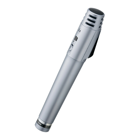
IR-200M
Update history
HS0905
Y
No.833-73-809-10
TABLE OF CONTENTS
NOTE ON REPAIR WORK SAFETY ......................................................................................................... 2
GENERAL DESCRIPTION ......................................................................................................................... 2
• IR-200M ........................................................................................................................................... 3
• IR-300M ........................................................................................................................................... 3
• IR-200M ........................................................................................................................................... 4
• IR-300M ........................................................................................................................................... 4
DISASSEMBLING INSTRUCTIONS (IR-200M) ......................................................................................... 5
• Measuring instruments to be used ................................................................................................... 6
• Connection diagram ......................................................................................................................... 6
• Adjustment points and input/output .................................................................................................. 7
• Adjustment and Check Method ........................................................................................................ 8
• At power on ...................................................................................................................................... 9
• From turning off the power switch to when the operation stops ....................................................... 9
• IR-200M ......................................................................................................................................... 10
• IR-300M ......................................................................................................................................... 10
• IR-200M ......................................................................................................................................... 11
• IR-300M ......................................................................................................................................... 12
SCHEMATIC DIAGRAMS
MAIN PCB ................................................................................................................................... 13
SUB PCB .................................................................................................................................... 14
BATT PCB ................................................................................................................................... 15
IR PCB ........................................................................................................................................ 16
SW PCB ...................................................................................................................................... 17
MAIN PCB ................................................................................................................................... 18
SUB PCB .................................................................................................................................... 18
Charge contact PCB ................................................................................................................... 18
PARTS LIST ................................................................................................................................ 18
BATT PCB ................................................................................................................................... 20
IR PCB ........................................................................................................................................ 20
SW PCB ...................................................................................................................................... 20
Charge contact PCB ................................................................................................................... 20
PARTS LIST ................................................................................................................................ 20
• IR-200M ......................................................................................................................................... 22
• IR-300M ......................................................................................................................................... 23
• Strap replacement procedure (IR-300M) ....................................................................................... 24
TABLE OF CONTENTS
IR-200M, IR-300M Y
1
Advertisement
Table of Contents

Subscribe to Our Youtube Channel
Related Manuals for Toa IR-200M


Summary of Contents for Toa IR-200M
-
Page 1: Table Of Contents
NOMENCLATURE AND FUNCTIONS • IR-200M ............................4 IR-200M, IR-300M • IR-300M ............................4 DISASSEMBLING INSTRUCTIONS (IR-200M) ..................5 ADJUSTMENT PROCEDURE • Measuring instruments to be used ....................6 • Connection diagram ......................... 6 • Adjustment points and input/output ....................7 •... -
Page 2: Note On Repair Work Safety
GENERAL DESCRIPTION Follow the instructions below, both to prevent accidents when making repairs and to ensure post-repair The IR-200M (hand-held type) and IR-300M (hands-free type) infrared wireless microphones are product safety. intended for speech applications and use unidirectional electret condenser microphone units featuring high sensitivity and clear sound. -
Page 3: Specifications
IR-200M, IR-300M Y SPECIFICATIONS • IR-200M • IR-300M Battery IR-200BT rechargeable battery for the infrared wireless microphone Battery IR-200BT rechargeable battery for the infrared wireless microphone (2 pieces) or AA alkaline dry cell battery (2 pieces). (2 pieces) or AA alkaline dry cell battery (2 pieces). -
Page 4: Nomenclature And Functions
IR-200M, IR-300M Y NOMENCLATURE AND FUNCTIONS • IR-200M • IR-300M [Top] [Front] [Side] Built-in microphone [Inside the battery case] [Front] [Rear] [Inside of the battery cover] 1. Power switch 5. Color label attachment area 1. Power switch / battery indicator 6. -
Page 5: Disassembling Instructions (Ir-200M)
IR-200M Y DISASSEMBLING INSTRUCTIONS (IR-200M) Circled number suffixed to the part name corresponds to the item number in the parts list on the exploded 5. Remove 1 screw securing the SUB PCB, disconnect 2 harnesses, then remove the SUB PCB and view page. -
Page 6: Adjustment Procedure
IR-200M, IR-300M Y ADJUSTMENT PROCEDURE 7. Remove 3 screws circled on the photo, then remove the windscreen frame, switch knob, switch PCB unit to be supplied as a service part is calibrated at the factory before shipment and further knob fixing clamp, and LED light. -
Page 7: Adjustment Points And Input/Output
IR-200M, IR-300M Y • Adjustment points and input/output · IR-200M · IR-300M · SW PCB (Component side) · SW PCB (Solder side) · MAIN PCB (Component side) External microphone RF level control Vt terminal input terminal Power selector switch Power switch... -
Page 8: Adjustment And Check Method
IR-200M, IR-300M Y • Adjustment and Check Method · IR-200M · IR-300M (Conditions) (Conditions) Room temperature : 15 - 35 °C (59 - 95 °F) Room temperature : 15 - 35 ºC (59 - 95 ºF) Power source : 2.4 ± 0.1 V DC Power source : 2.4 ±... -
Page 9: Operation Flow
OPERATION FLOW TROUBLESHOOTING [Common to the IR-200M and IR-300M] First, check and remedy the problem you are facing referring to the table below. If the symptom still does not improve, follow the flow chart on pages 10 to find the possible cause. - Page 10 IR-200M, IR-300M Y • IR-200M • IR-300M Microphone audio signals Microphone audio signals not output. not output. DC/DC converter's DC/DC converter's DC/DC converter (M102) or power DC/DC converter (M102) or power output voltage is 5.0 V. output voltage is 5.0 V.
-
Page 11: Block Diagrams And Operation Description
IR-200M Y BLOCK DIAGRAMS AND OPERATION DESCRIPTION • IR-200M PLL synthesizer section Oscillates transmitting frequency in conjunction with PLL. Amplifies signals Logarithmic- Amplifies high frequency Amplifies Controls power Serves as a buffer Serves as an IR bias control from microphone... -
Page 12: Ir-300M
IR-300M Y • IR-300M PLL synthesizer section Oscillates transmitting frequency in conjunction with PLL. Connecting external microphone turns off built-in electret microphone. Amplifies signals Logarithmic- Amplifies high frequency Amplifies Controls power Serves as a buffer Serves as an IR bias control from microphone compresses audio components of audio... -
Page 13: Ir-200M Main Pcb
IR-200M Y SCHEMATIC DIAGRAMS Ripple filter • IR-200M · MAIN PCB Buffer amplifier To CN202 of SUB PCB To CN203 of SUB PCB RF level control To CN200 of AF mute SUB PCB Power selector switch OFF detection Power switch... -
Page 14: Sub Pcb
IR-200M Y IR bias control · SUB PCB Infrared emitting LED To CN102 of To CN101 of MAIN PCB MAIN PCB LED driver LED driver RF amplifier Drive current control Drive current control To CN100 of MAIN PCB To Charge PCB... -
Page 15: Ir-300M Batt Pcb
IR-300M Y Ripple Filter • IR-300M · BATT PCB Buffer amplifier RF level control To CN200 of IR PCB Clock OFF detection (control) To Charge PCB Voltage assembly detector 1608Jumper dummy SCHEMATIC DIAGRAMS... -
Page 16: Ir Pcb
IR-300M Y · IR PCB IR bias control Power selector switch Infrared emitting LED LED driver LED driver RF amplifier Channel selector switch To CN303 of SW PCB To CN100 of Drive current control Drive current control BATT PCB To CN302 of SW PCB AF mute SCHEMATIC DIAGRAMS... -
Page 17: Sw Pcb
IR-300M Y · SW PCB To CN201 of Power IR PCB switch To CN202 of IR PCB 6dB ATT Low-pass filter Pre-emphasis To microphone Electret condenser microphone Microphone amplifier AF level control To MIC ASSY Compressor Tone oscillator SCHEMATIC DIAGRAMS... -
Page 18: Mounting Diagrams And Parts Lists
IR-200M Y MOUNTING DIAGRAMS AND PARTS LISTS • IR-200M · PARTS LIST · MAIN PCB (Part Code : 700-04-267-80) Designator Part Code Description BATT 124-04-438-40 CONTACT,IR200M (-) Viewed from parts mounting side Viewed from Conductor side BATT+ 124-04-217-9B CONTACT(+),BATTERY,WM1200 113-40-794-7X... - Page 19 IR-200M Y Designator Part Code Description Designator Part Code Description Designator Part Code Description Designator Part Code Description C226 113-40-794-7X GRM185B30J105KE25D LED202 111-08-374-50 LED, LN870F-04U(IR) R106 112-80-385-8X RESISTOR, 10K OHM 5%3/100 R224 dummy C227 dummy LED203 111-08-374-50 LED, LN870F-04U(IR) R107...
-
Page 20: Ir-300M
IR-300M Y • IR-300M · BATT PCB · SW PCB (Part Code : 700-04-268-30) (Part Code : 700-04-268-30) Viewed from parts mounting side Viewed from Conductor side Viewed from parts mounting side Viewed from Conductor side Caution The BATT PCB, SW PCB, and IR PCB are supplied in set. ·... - Page 21 IR-300M Y Designator Part Code Description Designator Part Code Description Designator Part Code Description Designator Part Code Description C222 113-40-794-7X GRM185B30J105KE25D L201 112-80-300-3X WIRE,JUMPER 112-80-365-6X RESISTOR 1.5K OHM 5%3/100 R211 112-80-300-3X WIRE,JUMPER C223 113-40-794-7X GRM185B30J105KE25D L202 114-05-256-4X COIL,LQH43CN100K03L 112-80-393-1X RESISTOR, 22K OHM 5%3/100 R212 112-80-300-3X WIRE,JUMPER...
-
Page 22: Exploded Views And Parts Lists
IR-200M Y EXPLODED VIEWS AND PARTS LISTS • IR-200M The Microphone unit and PC board assembly have been altered and the sealing spacer has been added. For details,see Change Notice No.833-73-809-1A. Caution Contact lug (BATT +) and coil spring (BATT -) can be supplied separately. - Page 23 IR-300M Y • IR-300M Charge contact PCB Caution The BATT PCB, SW PCB, and IR PCB are supplied in set. BATT PCB ACCESSORIES Caution IR PCB • Contact lugs (BATT +, BATT+2) and coil springs (BATT -, BATT-2) can be supplied separately. Refer to PCB drawings and parts list on p.
-
Page 24: Strap Replacement Procedure (Ir-300M)
IR-300M Y • Strap replacement procedure (IR-300M) 5. Clip and clamp the folded strap with the NP-AW8 until it locks in place. 1. Cut the existing strap on the side without the NP-AW8 using scissors to detach the strap from the NP-AW8 NP-AW8 NP-AW8...
Need help?
Do you have a question about the IR-200M and is the answer not in the manual?
Questions and answers