
Related Manuals for Toa IP-100RM


Summary of Contents for Toa IP-100RM
- Page 1 User’s manual IP remote control microphone IP-100RM Thanks for your purchase of TOA products IP-1000 series. Please read the manual carefully to ensure the machine operating in long time and fault-free. TOA Corporation...
- Page 2 Chapter 1 Safety precaution...
- Page 3 Chapter 1: safety precaution Please abide by the warning and the relevant safety tips. Please take this manual in convenient place after you reading the guide for future reference. Warning The sign means there is potential safety hazard, when operate wrong may result in death or serious injury.
- Page 4 Chapter 2 products description...
- Page 5 2.1 Summary 2.1 Summary IP-100RM IP remote control microphone is an IP remote microphone, it is used for general and emergency broadcast. It can receive broadcasting from server or other devices, and it also can initiate one zone or all zones broadcast, every key has the corresponding working status indicator, you can quickly obtain the working status of every zone and server through the working status indicator.
-
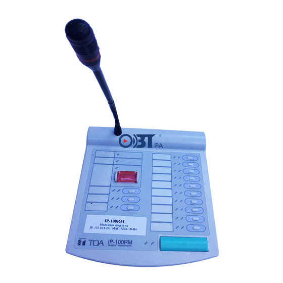
Page 6: Front View
Chapter 2: products description 2.2 Product interface description 2.2.1 IP remote control microphone IP-100RM Front view ① Power light: power input: green light is on, no power input: the light is off ② Trouble light: machine online, light is on, offline, orange light is off. - Page 7 Chapter 2: products description 2.2 Product interface description ⑥Functional key: users can define the functional key as the zone or task key. Zone key: every key means one or more zones, press the key means the zone was selected, and the corresponding zone light is on.
- Page 8 Chapter 2: products description 2.2 Product interface description Rear view Side view ①Power input interface: connect with DC24V/1A power adapter. ② LAN port: accessing cables, connect with the server. ③Input interface controlling & line input interface Input interface controlling: receiving the switch volume signal from the external controlled device. Line input interface: receiving the audio signal of other devices.
- Page 9 Chapter 2: products description 2.2 Products interface description 2.2.2 MIC Extension Unit RM-110 Front Side ① The name label ② The status light ③ The zone light ④ The functional key ⑤ The extension unit interface Every interface and function’s definition, please refer to page P2-2and P2-4.
- Page 10 Chapter 3 Wiring...
- Page 11 Chapter 3: wiring 3.1 MIC Wiring 3.1 IP-100RM Connection diagram RJ - 45 connector pin assignment and meaning as follows: Color Line pair Pin assignment Description ① External control input ( -) blue white CTRL_IN(-) ② External control input (+)...
- Page 12 Bracket A ................2 Bracket B ................1 Screw ................. 12 Step1: turning over the IP-100RM and RM-110, putting them together. Step 2: connecting two units by extension cable Step 3: using the 4 screws to connect the two units (marked and bracket B.
- Page 13 Chapter 4 System setting by browser...
- Page 14 Chapter 4: system setting by browser 4.1 Enter into browser 4.1 Enter into browser Step1: inputting MIC IP address in the IE browser (the defaults is 192.168.1.101), then press the Enter. Step 2: inputting the user name and password in the login window of Web page( the defaults is admin) Note: the user name and password have upper and lowercase.
- Page 15 Chapter 4: system setting by browser 4.2 Network parameters 4.2 Network parameters The unique MIC number, it can’t be same with terminals and other Device number hosts. The defaults is 2046, please don’t make any modification if not in Receiving port special situation.
- Page 16 Chapter 4: system setting by browser 4.3 Broadcasting parameters 4.3 Broadcasting parameters Input volume The total volume of the microphone is 0~15 in broadcasting. MIC audio output way is loudspeaker, line output, automatic identification in broadcasting. Loudspeaker: voice output from the loudspeaker of the MIC; Output selection Line output: the sound output from the earphone of the MIC;...
- Page 17 Chapter 4: system setting by browser 4.4 Key configuration 4.4 Key configuration Zone key: the key means zone (or area), the zone which is presented by key can be set in the “zone setting”. One key can present more than 10 zones (zone is not included in “non-zone” of the server). Zone number recognize the valid number within 3 digits, zones divide by comma.
- Page 18 Chapter 4: system setting by browser 4.5 Password modification 4.5 Password modification The account number and password of login page can be modified in the Web management parameters.
- Page 19 Chapter 4: system setting by browser 4.6 Web language modification 4.6 Web language modification The Web page of IP remote control microphone application (firmware) program support English and Chinese, the Web page of the bottom (BIOS) program isn’t support English.
- Page 20 Chapter 4: system setting by browser 4.7 Restart device 4.7 Restart device Clicking “restart device” to restart the device.
- Page 21 Chapter 4: system setting by browser 4.8 Resetting parameters 4.8 Resetting parameters Restore to factory settings: all parameters will be restored to the factory settings.
- Page 22 Chapter 4: system setting by browser 4.9 Firmware upgrade 4.9 Firmware upgrade Clicking the left mouse key “to the firmware upgrade mode” and enter into the firmware upgrade interface. Clicking browse, and select the correct upgrade file, clicking “firmware upgrade”, the device will automatically restart after upgrade.
- Page 23 Chapter 5 Operating description...
- Page 24 Chapter 5: operating description 5.1 Broadcast 5.1.1 Receiving broadcast IP remote control microphone can automatically receive broadcast from other devices or servers. During the receiving, press “broadcast” can stop the broadcasting. Receiving general broadcast, the related zone orange light will always on; Receiving the fire alarm broadcast, the related zone red light will always on.
- Page 25 Chapter 5: operating description 5.1 Broadcast 5.1.2.2 All zones broadcasting Step 1: pressing the fire alarm key of microphone pole, the fire alarm red light is always on. Step 2: pressing broadcast key to start full zones broadcasting, all zone red lights will be on. Step 3: talking to the appointed zone(microphone pole input) or broadcasting appointed audio program(line input), the specifications please refer to zone broadcasting step3 in page P5-1.
- Page 26 Chapter 5: operating description 5.2 Timing ringing 5.2.1 Pressing the key to trigger timing ringing task Step 1: Configuration key is task key. 1-1 In the server timing ringing task list, right click to binding the device. 1-2 Binding ID and key value of the terminal in the pop-up dialog box. ①Fill in ID number of the IP remote control microphone in the terminal number position;...
- Page 27 Chapter 5: operating description 5.2 Timing ringing Step 2: Press the corresponding task key, the server will execute timing ringing task immediately, the corresponding zone green light will be on at the same time, related zone orange light is on. Step 3: Repressing the task key, the task will be stopped, the corresponding zone and related light are off.
- Page 28 Chapter 5: operating description 5.3 Timing broadcasting 5.3.1 Press the key to trigger timing broadcasting task Step 1: Configuration key is task key 1-1 In the server timing broadcasting task list, right click to binding the terminal. 1-2 Binding ID and key value of the terminal in the pop-up dialog box, the specifications please refer to page P5-3.
- Page 29 Chapter 5: operating description 5.3 Timing broadcasting 5.3.3 Input controlling to trigger the timing broadcasting task Step1: Adding the timing broadcasting task in the server. 1-1 Triggering the appointed terminal, and inputting the ID number of the IP remote control microphone;...
- Page 30 Chapter 5: operating description 5.4 Fire alarm 5.4.1 Press the key to trigger fire alarm task Step 1: Configuration key is task key. 1-1 In the sever fire alarm task list, right click to binding the terminal. 1-2 Binding ID and key value of the terminal in the pop-up dialog box, the specifications please refer to page P5-3.
- Page 31 Chapter 5: operating description 5.4 Fire alarm 5.4.3 Input controlling to trigger the fire alarm task Step 1: Adding the fire alarm task in the server. 1-1 Triggering device select alarm terminal, and inputting the ID number of the IP remote control microphone;...
- Page 32 Chapter 5: operating description 5.5 Recording Server can automatically recording and save all broadcasting OF IP remote control microphone, the user can check the recording files by recording tools. Step 1: Select “auto-recording in broadcasting” in the server advanced setting.
- Page 33 Chapter 5: operating description 5.5 Recording Step 2: Recording tool configuration 2-1 Running recording tool 2-2 Clicking setting, after recording parameters configuration then click “OK”. 2-2 Clicking “restart server” to restart the recording tool. 5-10...
- Page 34 Chapter 5: operating description 5.5 Recording Step 3: Checking and listening recording files. 3-1 Please select screening condition (date or terminal name), and inputting key words. 3-2 Clicking , the recording tool will indicate the qualified recording file. 3-3 Selecting target file in the recording file list, clicking to listening.
- Page 35 Chapter 6 Appendix...
- Page 36 6.1Specification 6.1.1 IP remote control microphone IP-100RM Model number IP-100RM Power Normally input DC24V maximum adaptation range is DC12~25V Less than 200mA(IP-100RM)、less than 500mA(connect with 9 RM-110) Current consumption @24V Balance,1Vrms(Max:2Vrms)@10KΩ Audio input Imbalance, 1Vrms @10kΩ or imbalance,11.25mW@32Ω Audio output Built-in monitor speaker Maximum power output: 1.0W...
- Page 37 TOA Corporation 201611...
Need help?
Do you have a question about the IP-100RM and is the answer not in the manual?
Questions and answers