Table of Contents
Advertisement
Quick Links
0 .. DECLARATION OF CONFORMITY AND WARNINGS FOR THE INSTALLER ................................................................. 2
1 .. DESCRIPTION AND TECHNICAL SPECIFICATIONS .................................................................................................. 3
1.1 DIMENSIONS ........................................................................................................................................................... 3
1.2 MECHANICAL PREPARATIONS ................................................................................................................................. 3
3 .. INSTALLING THE AUTOMATED SYSTEM ................................................................................................................. 4
3.1 PRELIMINARY CHECKS ............................................................................................................................................ 4
3.2 INSTALLATION DIMENSIONS .................................................................................................................................... 4
3.3 INSTALLING THE OPERATOR .................................................................................................................................... 4
4 .. TRAVEL LIMIT UNIT ................................................................................................................................................ 6
5 .. ELECTRICAL CONNECTIONS ................................................................................................................................. 6
5.1 BUTTON-BOARD OR SELECTOR 230 Vac ................................................................................................................. 6
5.2 COMMANDS WITH 200BT CONTROL BOARD ......................................................................................................... 6
5.3 COMMANDS WITH 200MPS CONTROL BOARD ...................................................................................................... 6
6 .. START-UP OF THE SYSTEM .................................................................................................................................... 7
6.1 MANUAL ADJUSTMENT OF THE TRAVEL-LIMIT DEVICES ............................................................................................. 7
7 .. INSTALLING THE ELECTRO-BRAKE (optional) ......................................................................................................... 7
8 .. CONNECTION OF TWO R180/280 UNITS ............................................................................................................... 8
INDEX
(standard system) .............................................................................................................. 4
1
Advertisement
Table of Contents

Related Manuals for FAAC R180


Summary of Contents for FAAC R180
-
Page 1: Table Of Contents
5.3 COMMANDS WITH 200MPS CONTROL BOARD ...................... 6 6 .. START-UP OF THE SYSTEM ............................ 7 6.1 MANUAL ADJUSTMENT OF THE TRAVEL-LIMIT DEVICES ..................... 7 7 .. INSTALLING THE ELECTRO-BRAKE (optional) ......................7 8 .. CONNECTION OF TWO R180/280 UNITS ....................... 8... -
Page 2: Declaration Of Conformity And Warnings For The Installer
FAAC a source of danger. are used. 6) FAAC declines all liability caused by improper use or use other than that 19) For maintenance, strictly use original parts by FAAC. for which the automated system was intended. -
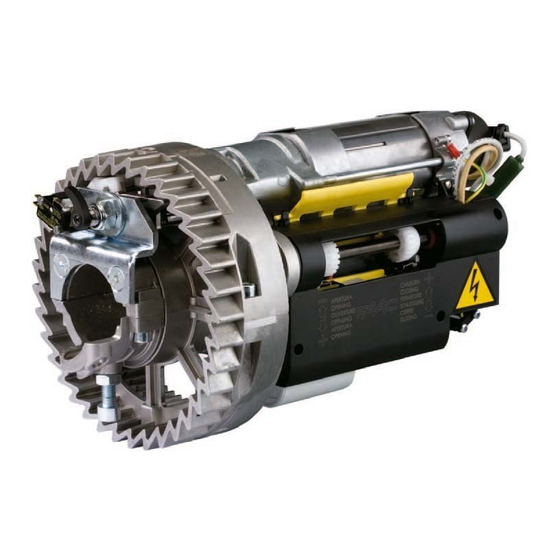
Page 3: Description And Technical Specifications
The following instructions apply to automated systems: 1.1 DIMENSIONS R 180 - R 280 The FAAC automated system for moving rolling shutters consists of a drive crown gear and a central body including the drive unit, the reduction components and the travel-limit unit. -
Page 4: Electric Preparations (Standard System)
… To install two R180 or R280 operators on a shutter having a width of over 4.5 meters, please refer to chapter 8 on page 8. - Page 5 If, in chapter 1.2, you have measured a winding pulley diameter Using the hole on the flange in Fig.7 ref. as a reference, drill a of 220 mm, you must fit the crown adapters, as shown in Fig. 9. through hole (diam 10.5 mm) on the winding shaft; Couple the adapters in the housings on the crown.
-
Page 6: Travel Limit Unit
Open Close shutter. Fig. 13 In the R180 and R280 applications the travel limit devices are integrated ELECTRICAL CONNECTIONS and, therefore, the dedicated connections on the 200BT board must be short circuited. The gearmotors for shutters R180 and R280 can be commanded by direct power, supplied by a 230 VAC selector, or by control boards In Figure 13 jumper connect terminals 2 and 3 to terminal 1. -
Page 7: Start-Up Of The System
In fact, the electro-brake acts on the motor shaft, locking it at the end The travel limit unit of automated system R180 and R280, was designed of each electric movement, thus ensuring that the shutter cannot... -
Page 8: Connection Of Two R180/280 Units
8 CONNECTION OF TWO R180/280 UNITS For shutters with a width of over 4.5 meters, we advise installing two R180 or R280 operators at the sides of the shutter as shown in Fig. 20. Fig. 18 Assemble the release knob in Figure 18, taking care to fully fasten the regulator in ref.
Need help?
Do you have a question about the R180 and is the answer not in the manual?
Questions and answers