Advertisement
Quick Links
Advertisement

Related Manuals for FAAC 740 D


Summary of Contents for FAAC 740 D
- Page 1 740 D...
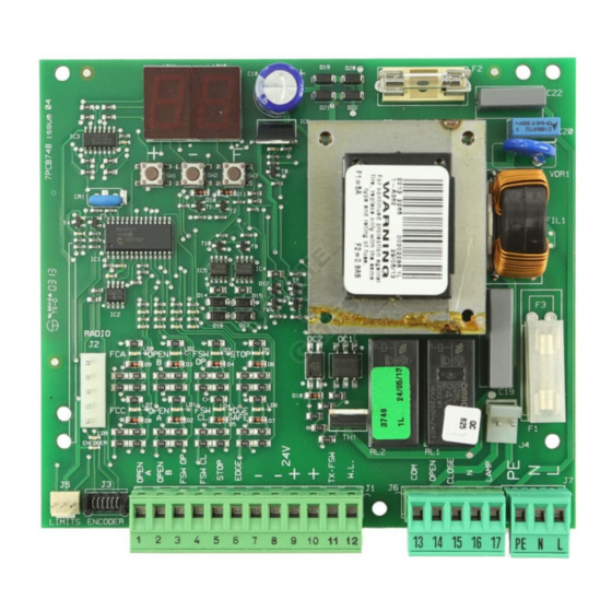
- Page 2 CONTROL BOARD 740 D 3. LAYOUT AND COMPONENTS 1. WARNINGS Before attempting any work on the control board (connections, maintenan- ce), always turn off power. Install, upstream of the system, a differential thermal breaker with adequate tripping threshold. Connect the earth cable to the appropriate terminal on the J7 connector of the equipment (see fig.2).
- Page 3 4.1. Connection of photocells and safety devices Connection of an “edge” safety device Connection of an “edge” safety device Before connecting the photocells (or other devices) we advise you to select the type of operation according to the movement area they have to protect (see fig.3): Opening or Closing...
- Page 4 Connection of a pair of closing photocells and a pair of Connection of a pair of closing photocells and a pair of Connection of two pairs of closing photocells and two edge safety Connection of two pairs of closing photocells and two edge safety opening/closing photocells opening/closing photocells devices...
- Page 5 • 4.5. Connector J2 - Rapid connection to Minidec, Decoder and RP FSW OP - Opening safety devices contact (terminal 3): The purpose of the opening safety devices is to protect the leaf movement area This is used for rapid connection of Minidec, Decoder and RP receivers (see during opening.
- Page 6 5. PROGRAMMING ADVANCED PROGRAMMING To program operation of the automated system, you have to access the Display Function Default “PROGRAMMING” mode. Programming is split into two parts: BASIC and ADVANCED. FINAL BRAKING: When the gate engages the opening or closing 5.1.
-
Page 7: Automated System Test
ADVANCED PROGRAMMING ADVANCED PROGRAMMING Display Function Default Display Function Default ENCODER: CYCLE PROGRAMMING: If the encoder is used, you may select its pre- For setting countdown of system operation cycles. sence. Settable (in thousands) from thousand If the encoder is present and enabled, “decele- cycles.
Need help?
Do you have a question about the 740 D and is the answer not in the manual?
Questions and answers