
Related Manuals for Pfeiffer Vacuum HIQUAD QMG 700


Summary of Contents for Pfeiffer Vacuum HIQUAD QMG 700
- Page 1 OPERATING INSTRUCTIONS Translation of the original instructions HIQUAD™ QMG 700 Quadrupole Mass Spectrometry System...
-
Page 2: Trademarks
The information contained in this manual is believed to be accurate and reliable. However, Pfeiffer Vacuum assumes no responsibility for its use and shall not be liable for any special, incidental, or consequential damages related to the use of this product. -
Page 3: Table Of Contents
Contents Contents Trademarks............2 Disclaimer . -
Page 4: Safety
Safety Safety Symbols Used DANGER Information on preventing any kind of physical injury. WARNING Information on preventing extensive equipment and environmental damage. CAUTION Information on correct handling or use. Disregard can lead to malfunctions or minor equipment damage. NOTE All work described in this document may only be carried out by persons who have suitable technical training and the necessary experience or who have been instructed by the end-user of the product. -
Page 5: Liability And Warranty
Safety Liability and Warranty Pfeiffer Vacuum assumes no liability and the warranty becomes null and void if the custodian or third parties: disregard the information in this document use the product in a non-conforming manner make any kind of changes (modifications, alterations, etc.) to the product ... -
Page 6: System Overview
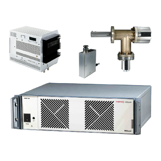
System Overview System Overview System components The QMG 700 comprises of the controller QMS 700 (system chassis SC 700 including the modules: QC 700, FB 711, IS 716, HV 701, HV 702, and IO 700). From the 42x system the modules RF generators (QMH 4xx-x), analyzers (QMA 4x0), the electrometer preamplifier (EP 422), and the ion counter preamplifier CP 400 are utilized as well. -
Page 7: Qmg 700 Quadrupole Mass Spectrometer, Components And Modules
System Overview QMG 700 Quadrupole Mass Spectrometer, Components and Modules Controller QMS 700 Controller Comprises the system chassis SC 700 and the modules described below. SC 700 System Chassis Comprises the power supply, the internal bus plane and the system ventilation. It houses the modules described below. - Page 8 System Overview HV 701 High Voltage Supply Supplies high voltage to the SEM 217 for positive ion detection. HV 702 High Voltage Supply Supplies high voltage to the SEM 218 for positive ion detection or the required voltages to the SEM 217 for positive and negative ion detection (biased potentials) IO 700 I/O System...
- Page 9 System Overview CP 400 Ion Counter Preamplifier Comprises the pulse coupling, amplifier, and pulse height discriminator with adjustable threshold. It is installed directly on the QMA 4x0 with 90°off-axis SEM. QMH 4xx HF-Generator Produces the high frequency voltage required for mass separation (separate operating instructions).
-
Page 10: Technical Data
Technical Data Technical Data General This information applies to all QMS 700 modules unless specified otherwise. Ambient conditions Temperature Storage –40 °C … +65 °C Operation +5 °C … +40 °C Relative humidity 80% up to +31 °C, decreasing linearly to 50% at +40 °C indoors, altitude up to 2000 m NN Type of protection IP 30... - Page 11 Technical Data Dimensions [mm] Weight 7.5 kg (without modules) Module slots 18 (4U each) System expansion In order to expand system functionality, up to four SC 700 chassis can be cascaded. Two versions of the SC 700 chassis are available: ...
-
Page 12: Quadrupole Controller Qc 700
Technical Data Connector for optional chassis expansion, must be terminated with a resistor if not used. BUS IN Connector for optional chassis expansion, must be terminated with a resistor if not used. BUS OUT 24 VDC power supply CAUTION This 24 VDC supply may only be used for an external bus node. Do not use it for any other purpose. - Page 13 Technical Data Operation Modes and Parameters Number of measuring channels Operation modes MONO- / MULTI channel Measuring cycles 1 ... 10,000 or REPEAT Time required for a 100 ... 200 s (at min. PAUSE in Cycle) channel change Mass scan modes mass-MODE Measuring method SCAN-N...
- Page 14 Technical Data Measurement ranges and resolution Detector Measurement Modes Resolution type ranges FARAD,SEM FIX- and … 10 A fsd 16 bit (per range) AUTO-Range EXTERN GAIN 1: ±10.240 V FIX-Range 16 bit GAIN 10: ±1.024 V ION-CNT AUTO-Range in mass-MODE: …...
- Page 15 Technical Data Electrical Connections QC 700 Connector for RF generators (QMH 4xx) (D-Sub 25 pin, female). QMH connection Ethernet connector (RJ45). LAN connection The interface status is indicated by two LEDs integrated in the RJ45 connector: RJ45 Status Meaning Green green data transfer rate 100 Mbit/s...
- Page 16 Technical Data CTRL connector, pin assignment Signal Signal type Description via 100 Ω to GND via 100 Ω to GND via 100 Ω to GND RUN IN TTL input input for external start of measuring cycle, low true, internal pull-up 5.6 kΩ to +5 V SYNC IN TTL input reserved for future use, low true,...
-
Page 17: Ion Supply Is 716
Technical Data Ion Supply IS 716 Connector for analyzer AUX I/O Connector for filament protection and reserved I/Os General Compatibility System chassis SC 700 Number of slots occupied Modules per system max. 2 Slot No. Weight 1 kg Filament power supply Voltage 0 …... - Page 18 Technical Data Potentials IS 716 DANGER The QMS 700 may not be switched on without a correctly connected QMA cable. DANGER The maximum current of the external voltage source V0 has to be reliably limited to 2 mA. Ion potentials at max. pos. IONREF (+150 V), V1 referenced to V0 V2...V8 referenced to V1...
- Page 19 Technical Data Ion potential at max. neg. V1 referenced to V0 IONREF (–150 V), V2...V8 referenced to V1 negative polarity V9 referenced to V2 QMA-GND IONREF (V1) Electrode Range Nominal Resolution Offset Gain Potential Name Current Error at Degas V1 IONREF 2.5 mA 20 mV 120 mV 1.6% +550 V...
- Page 20 Technical Data Electrical Connections IS 716 QMA connector pin assignment DANGER The QMS 700 may not be switched on without a correctly connected QMA cable. 16 pin LEMO socket, view on IS 716 Signal Description QMA GND SPEC SRC RET Reference signal for SPEC SRC ON V6, inner Deflection V3, Focus...
-
Page 21: High Voltage Supply Hv 701
Technical Data AUX I/O connector pin assignment D-Sub 9 pin, female view on IS 716 Signal Signal type Description EXT PROT 24 V digital input filament protection input DI RES 1 TTL input DI RES 3 TTL input DO RES 1 TTL input DO RES 2 TTL input... -
Page 22: High Voltage Supply Hv 702
Technical Data High Voltage Supply HV 702 High voltage connector HV– High voltage connector Conversion dynode- connector General Compatibility system chassis SC 700 Number of slots occupied Modules per system max. 2 Slot No. 8 … 10 Weight 0.54 kg High voltage power supply Bias voltage supply... - Page 23 Technical Data Configuration and wiring of the HV 702 depends on operation mode: Operation modes Operation Description HV 702 connections Principal diagram mode HV 702 Shorting plug installed SEM HV– not used QMA, HV HV 702 Shorting plug installed QMA, HV ...
-
Page 24: I/O System Io 700
Technical Data I/O System IO 700 NOTE ® Digital and analog input/output sub-modules made by WAGO are used in the IO 700 (detailed description block diagram and connection diagram in appendix). ® WAGO modules Cable glands General Compatibility System chassis SC 700 Number of slots occupied Modules per system Max. - Page 25 Technical Data Analog outputs Sub-module type used WAGO 750-559 Number of channels Output voltage 0 … +10 V Resolution 12 bit Load impedance ≥5 kΩ Conversion time 10 ms Refresh rate 10 ms Reference potential GND terminals are connected together in groups of four channels.
-
Page 26: Field Bus Fb 711
(5 Hz) acyclic, fatal hardware error- or runtime error detected 3 (5 Hz) 8 contact a Pfeiffer Vacuum service (0.75 Hz) center. green cyclic, no error detected FB 711 (5 Hz) FB 711 is ready for operation and makes... -
Page 27: Electrometer Preamplifier Ep 422
Technical Data Electrometer Preamplifier EP 422 Analyzer connection Cable to QMH General Location Directly connected to analyzer Interfaces QMH and QMA Modules per system Max. 2 Weight 0.15 kg Power supply (Provided by QMS 700) Voltage 16 V (0.2 V, 10 mV ripple) Current 10 mA Amplifier specifications... -
Page 28: Ion Counter Preamplifier Cp 400
Technical Data Dimensions [mm] 3.10 Ion Counter Preamplifier CP 400 NOTE Function and technical data of the CP 400 are described separately. Connection to QC 700 High voltage connectors HV– SEM connection flange General Compatibility QMG 700 system Location SEM feedthrough at QMA Interfaces QMA, QC 700 and HV 701/HV 702 Modules per system... - Page 29 Technical Data QC connector pin assignment D-Sub,15 pin, male view on CP 400 Signal Signal type, description QMA GND Identification – OUT– ECL output OUT+ ECL output Supply voltage LEVEL– Threshold voltage LEVEL+ Threshold voltage V– Supply voltage 9 … 15 not connected –...
-
Page 30: Installation
Installation Installation General DANGER Putting a product which presents a visible damage into operation can be extremely hazardous. If the product presents a visible damage do not put it into operation and make sure it is not inadvertently put into operation. DANGER The local line voltage ratings must correspond to the nominal voltage of the product (... -
Page 31: Qmg 700 Overall System
Installation QMG 700 Overall System Install peripheral components such as the analyzer, RF generator, etc. in accordance with the information in the respective operation instructions. All components involved must be grounded to a single point. Utilization of a single power distributor is recommended. -
Page 32: Installation/Replacement Of Modules In The System Chassis
Installation Installation of plastic 1 Turn over the unit and plug the plastic feet into the four holes as shown. feet 2 Push in the protruding plastic pins completely with a screwdriver handle or a similar tool of appropriate size. 3 The feet are now locked in the bottom plate. - Page 33 Installation Screw driver type "Pozidriv", size1 Required tool NOTE Modules are installed in the order shown below (standard configuration). All screws must be tight for a firm mechanical support and reliable electrical contact. Unused slots must be covered with correctly fitting blank panels to ensure safety and adequate ventilation of the unit.
-
Page 34: Installation Of The Fieldbus Fb 711
Installation Installation of the Fieldbus FB 711 The optional Fieldbus interface can be added according to the following description. Screwdriver size 2 Required tool 1 Remove the QC 700 from the system chassis. Procedure 2 Slide out the cover plates of QC 700 and FB 711 handles. 3 Remove the handle of the QC 700. -
Page 35: Electrometer Preamplifier Ep 422
Installation Electrometer preamplifier EP 422 The EP 422 is located directly at the analyzer. 1 Connect the EP 422 into the corresponding connector at the QMA. 2 Make sure the EP 422 is not touching adjacent connectors. 3 Fasten the knurled nut. 4 Connect the control cables to the connectors ep1 and/or ep2 at the QMH 4xx. -
Page 36: System Wiring
Installation System Wiring System wiring depends on the operation mode. On the following pages, wiring and material requirements of three operation modes are described. NOTE 90°-SEM and CP operation modes each require supplementary wiring to the basic wiring described below. Basic wiring Faraday (Valid for HV 701 and HV 702 installations.) operation mode... - Page 37 Installation Wiring 90° SEM operation mode NOTE (with HV 701) The 90° SEM operation mode also requires the basic wiring described previously. Required cables and shorting plugs Cable Length Order number Interconnection EP 422 (2) – QMH 4xx 0.85 m –...
- Page 38 Installation Wiring CP operation mode (ion counter) NOTE (with HV 701) The CP operation mode also requires the basic wiring described previously. Required cables and shorting plug Cable Length Order number HV interconnection HV 701 – CP 400 BG541978-T 10 m BG541979-T Interconnection QC 700 –...
- Page 39 Installation Wiring 90° SEM operation mode NOTE (with HV 702, operation mode 0) The 90° SEM operation mode also requires the basic wiring described previously. Required cables and shorting plugs Cable Length Order number Interconnection EP 422 (2) – QMH 4xx 0.85 m –...
- Page 40 Installation Wiring CD operation mode (with HV 702, NOTE operation mode 1) The conversion dynode (CD) operation mode also requires the basic wiring described previously. Required cables and shorting plugs Cable Length Order number Interconnection EP 422 (2) – QMH 4xx 0.85 m –...
- Page 41 Installation Wiring CP operation mode (ion counter) NOTE (with HV 702, operation mode 2 The CP operation mode also requires the basic wiring described previously. and 3) Required cables and shorting plugs Cable Length Order number HV interconnection HV 702 – CP 400 BG541978-T 10 m BG541979-T...
-
Page 42: 4.10 Pc Connection
Installation 4.10 PC Connection Since the QMS 700 does not have a local control panel, it is operated via a PC interface or as a device in a network. There are various ways to interconnect a QMS 700 (QC 700) and a PC: LAN interface ... -
Page 43: 4.11 Io 700 Wiring
Installation 4.11 IO 700 Wiring Options are factory installed if they have been ordered together with the system. They can also be installed in the field at any time. DANGER Work on an open unit may only be performed by skilled personnel. Switch off the unit before any manipulations on the equipment. -
Page 44: Operation
Operation Operation Initial Start Up DANGER Verify the correct installation of all system components and compliance with technical data before equipment is switched on. Note before start up Before the system is started, check the following: Mains switch of QMS 700 is in OFF (O) position ... -
Page 45: Maintenance
Maintenance Maintenance Maintenance of the Air Filter The QMS 700 draws ventilation air through a set of openings in the front panel. The air filter in front of these openings has to be cleaned/replaced before excessive dust accumulation restricts the air circulation. NOTE Intervals depend on the results of regular optical inspections and the local dust production. -
Page 46: Repair
Protection against electrostatic discharges (ESD) is absolutely essential, otherwise the Pfeiffer Vacuum warranty becomes null and void. Replacing the Mains Fuse A defective mains fuse will cause the LED DC to stay dark even if mains voltage is applied and the mains switch is in ON position ( I ). -
Page 47: Accessories
Accessories Accessories When ordering, always indicate: all information on the product name plate description and ordering number according to list Ordering number Replacement dust filter 451-067 Blank panel 4U (20 mm) 46-0022 Blank panel 8U (40.3 mm) 46-0023 Blank panel 28U (141.9 mm) 46-0024 Screws for blank panels... -
Page 48: Storage
Storage Storage CAUTION Electronic component. Inappropriate storage (static electricity, humidity etc.) can damage electronic components. Store product in antistatic container. Observe the corresponding specifications in the Technical Data. -
Page 49: Returning The Product
Contaminated products (e.g. radioactive, toxic, caustic or biological hazard) can be detrimental to health and environment. Products returned to Pfeiffer Vacuum should preferably be free of harmful substances. Adhere to the forwarding regulations of all involved countries and forwarding companies and enclose a duly completed declaration of contamination *). -
Page 50: Disposal
Disposal Disposal DANGER Contaminated parts. Contaminated parts can be detrimental to health and environment. Before beginning to work, find out whether any parts are contaminated. Adhere to the relevant regulations and take the necessary precautions when handling contaminated parts. WARNING Substances detrimental to the environment. -
Page 51: Appendix A Connection Diagram
Connection Diagram Appendix A Connection Diagram... -
Page 52: Appendix B Literature
Appendix B Literature www.pfeiffer-vacuum.com Operating instructions RF Generator QMH 400 / 410 BG 5982 BEN Pfeiffer Vacuum GmbH, 35614 Asslar, Germany Operating instructions Analyzer QMA 400 / 410 / 430 BG 5983 BEN Pfeiffer Vacuum GmbH, 35614 Asslar, Germany ... -
Page 53: Declaration Of Conformity
EMC - Measurement, Control & Laboratory Equipment RoHS: Due to the classification of this product it is currently exempt from the RoHS directive until 2017. Signatures: Pfeiffer Vacuum GmbH Berliner Straße 43 35614 Asslar Germany (Dr. Ulrich von Hülsen) 2016-05-17... - Page 54 VACUUM SOLUTIONS FROM A SINGLE SOURCE Pfeiffer Vacuum stands for innovative and custom vacuum solutions worldwide, technological perfection, competent advice and reliable service. COMPLETE RANGE OF PRODUCTS From a single component to complex systems: We are the only supplier of vacuum technology that provides a complete product portfolio.
Need help?
Do you have a question about the HIQUAD QMG 700 and is the answer not in the manual?
Questions and answers