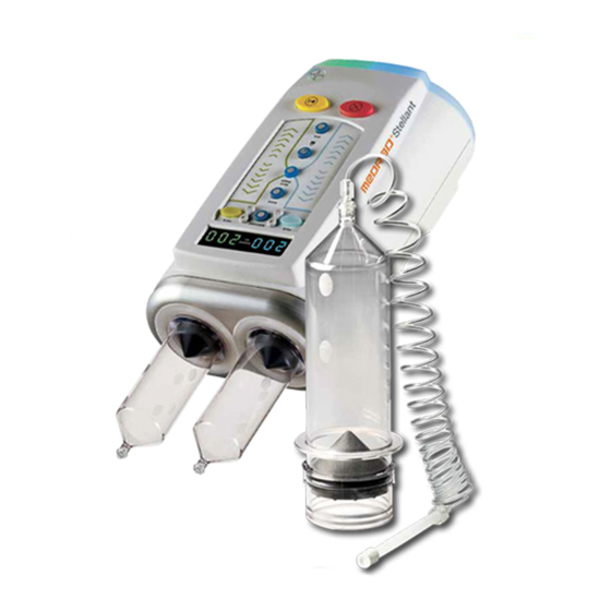
Bayer HealthCare MEDRAD Stellant Operation And Installation Manual
Imaging system interface (isi) 700 module ct injection system
Hide thumbs
Also See for MEDRAD Stellant:
- Operation manual (104 pages) ,
- Instructions for use manual (10 pages)

Related Manuals for Bayer HealthCare MEDRAD Stellant


Summary of Contents for Bayer HealthCare MEDRAD Stellant
- Page 1 Operation and Installation Manual MEDRAD® Stellant Imaging System Interface (ISI) 700 Module...
- Page 3 English ® MEDRAD Stellant Imaging System Interface (ISI) 700 Module Operation and Installation Manual Operating specifications, options, accessories, and feature availability may vary by country. Check with your local product representative and country- specific operating instructions. ® The MEDRAD Stellant Imaging System Interface (ISI) 700 module has an expected service life* of 7 years from the date of product installation when operated according to the instructions provided with this device.
- Page 4 ® MEDRAD Stellant ISI 700 Module Operation and Installation Manual...
-
Page 5: Table Of Contents
Table Of Contents Introduction ..............1 Installation . - Page 6 ® MEDRAD Stellant ISI 700 Module Operation and Installation Manual...
-
Page 7: Introduction
® Introduction The MEDRAD Stellant Imaging System Interface (ISI) 700 Module (Catalog Number: ISI 700) is an option that allows an injector from Bayer to interface with a CT scanner. It obtains its power from a hospital grade wall outlet. It interacts with an injector and scanner through direct cable connection. -
Page 8: Monitors
® MEDRAD Stellant ISI 700 Module Operation and Installation Manual ® In some countries, the MEDRAD Stellant CT Injection system may be purchased with a Monitors ® choice of two monitors, shown below - "Display and Control Unit (DCU)" and "Certegra Workstation."... - Page 9 Keep Dry (ISO 15223-1, 5.3.4). Medical - General Medical Equipment As To Electrical Shock, Fire, and Mechanical Hazards Only In accordance with ANSI/ AAMI ES60601-1 (2005) + AMD 1 (2012) CAN/CSA-C22.2 No. 60601-1 (2014) Indicates that this device conforms to the requirements of the European Medical Device Directive 93/42/EEC.
- Page 10 ® MEDRAD Stellant ISI 700 Module Operation and Installation Manual IPX1 Code that specifies the degree of protection provided by the enclosure against vertically falling water drops (IEC 60529) Identifies the Protective Earth Ground point. (IEC TR 60878, 5019) See accompanying documentation. This symbol indicates the user shall refer to the instructions-for-use to ensure safe operation.
-
Page 11: Warnings
Procedure request can be initiated from EITHER the scanner or the injector. When either or both system symbol (Injector and Scanner) is gray, that system is not ready and injection will not proceed. When both the symbols are highlighted in yellow and flashing, both the systems is ready and the injection can proceed. -
Page 12: Cautions
® MEDRAD Stellant ISI 700 Module Operation and Installation Manual System damage may occur if voltage is applied to J1 Pins 16, 18, 23, 25, 27, or 33. Only Cautions connect these pins to isolated switch or relay contacts in the scanner. Damage can occur as a result of incorrect voltage. - Page 13 To install the ISI module: Unpack the ISI module. Connect the ISI module communication cable to injector base. Connect interface cable from scanner to ISI module. Connect the power cable to the ISI module. Ensure power indicator is illuminated. 1. ISI module assembly 2.
-
Page 14: Operational Checkout
® MEDRAD Stellant ISI 700 Module Operation and Installation Manual If the base has a hub installed, remove it and replace it with a switch, catalog number SWITCH301 (pictured below). ® ® MEDRAD Stellant CT Injection System with Certegra Workstation (Stellant CWS) and ®... -
Page 15: Configuration
Configuration Configure the ISI module on the injector setup screen by first accessing Setup. To access Setup, do the following depending on your Monitor. If you have the Display and Control Unit (DCU), press the setup button, below. Note that this button is a physical, rubber button and not a touchscreen button. b. -
Page 16: Injector Head Indicator Lights
® MEDRAD Stellant ISI 700 Module Operation and Installation Manual the scan immediately regardless of you pressing "OK," "Same Patient," or "New Patient" on the injection complete window. It is recommended not to program Hold phases in the injection protocol when using the ISI feature unless directed by the scanner manufacturer. -
Page 17: Scan Delay
Scan Delay If the injection system software version is 17A or higher, the scan delay must be programmed from the scanner. Maintenance: A periodic inspection of the ISI Interface Cables is a recommended to ensure ISI Module Cables that there are no obvious defects, such as cuts or breaks in the cable, which could disrupt signal integrity. - Page 18 ® MEDRAD Stellant ISI 700 Module Operation and Installation Manual Display and Control Unit (DCU): The ISI module did not pass a self-test. Unplug the power cable to the ISI module, "ISI module failure" then re-plug. Certegra Workstation: "ISI module failure" NOTE: If the problem cannot be rectified, go to the injector setup screen to configure ISI "Off."...
- Page 19 Signals and Descriptions *The ISI scanner interface is a 37-pin D shell connector (J1), located on the ISI module. The following signals are provided to work properly with the scanner. **The scanner manufacturer is responsible for assuring the scanner will not respond to a Scan Start signal until it is safe to do so.
-
Page 20: Environmental Specifications
® MEDRAD Stellant ISI 700 Module Operation and Installation Manual Non-Operating: (Transportation and Storage) Environmental Specifications Temperature: C to 70 C (-13 F to +158 Humidity: 5% to 100% R.H., non-condensing Air Pressure: 48 kPa to 110 kPa Operating: (The system may not meet all performance specifications if operated outside of the following conditions.) Temperature: C to + 40... - Page 21 Mode of Operation: Per IEC 60601-1 the mode of operation for the ISI module is continuous. It is capable of operation under normal load for an unlimited period, without excessive temperature being developed.
- Page 22 ® MEDRAD Stellant ISI 700 Module Operation and Installation Manual...
-
Page 23: Appendix A - Compliance To Iec 60601-1-2 / 2Nd, 3Rd, And 4Th Editions
Appendix A - Compliance to IEC 60601-1-2 / 2nd, 3rd, and 4th Editions ® The MEDRAD Stellant Imaging System Interface (ISI) 700 Module complies with the requirements of: IEC 60601-1-2: Medical electrical equipment – Part 1-2: General requirements for basic safety and essential performance – Collateral standard: Electromagnetic compatibility –... - Page 24 ® MEDRAD Stellant ISI 700 Module Operation and Installation Manual WARNING: Portable RF communications equipment (including peripherals such as antenna cables and external antennas) should be used no closer than 30 cm (12 inches) to any part of the injection system unless a greater separation distance is required as indicated by the equation.
- Page 25 THE SYSTEM REQUIRES SPECIAL PRECAUTIONS REGARDING EMC. Install and put into service according to the EMC information provided below: Guidance and manufacturer's declaration - electromagnetic emissions The system is intended for use in the electromagnetic environment specified below. The customer or user of the system should assure that it is used in such an environment.
- Page 26 ® MEDRAD Stellant ISI 700 Module Operation and Installation Manual Guidance and manufacturer's declaration - electromagnetic immunity The system is intended for use in the electromagnetic environment specified below. The customer or user of the system should assure that it is used in such an environment.
-
Page 27: Index
Index Cables, 11 Cautions, 6 Certifications, 1 Configuration, 9 Contraindications, 1 Disclaimers, 1 Imaging System Interface (ISI), 1, 11 Injector Head Indicator Lights 10 Installation, 6 J1 Pins, 13 Maintenance, 11 Messages and Descriptions, 11 Operation, Details of, 10 Operation, Overview, 9 Operational Checkout, 8 Rating, maximum, 12 Rating, minimum, 12... - Page 28 ® MEDRAD Stellant ISI 700 Module Operation and Installation Manual...
- Page 30 All patient data that appear in this document are fictitious. No actual patient information is shown. Bayer, the Bayer Cross, MEDRAD, Imaxeon, Stellant, Stellant FLEX, MEDRAD Stellant, MEDRAD Stellant FLEX, P3T, VirtualCare, and Certegra are trademarks owned by and/or registered to Bayer in the U.S. and/or other countries. Other trademarks and company names mentioned herein are properties of their respective owners and are used herein solely for informational purposes.
Need help?
Do you have a question about the MEDRAD Stellant and is the answer not in the manual?
Questions and answers